Mercedes w204 is the 3rd generation of C-class cars of the German automaker Mercedes-Benz which was produced in 2007, 2008, 2009, 2010, 2011, 2012, 2013 and 2014 with various engine options (C180 cdi, C230, C280, C 300 (4MATIC), C350, C63 AMG etc.). During this time, the model has been restyled. In this material, we will show the locations of electronic control units, a detailed description of the fuses and relays Mercedes 204 with box diagrams and photo examples of their execution. Select the fuse responsible for the cigarette lighter.

The location of the blocks and the purpose of the elements in them may differ from those shown and depend on the year of manufacture and the level of electrical equipment of your car.
Contents
Location
Control units
The general layout of the control units in the Mercedes w204

Assignment
| 1 | ABS electronic control unit |
| 2 | Air conditioning electronic control unit – in the heater control panel |
| 3 | A/C/Heater Fan Motor Control Module – Near Heater Fan Motor |
| 4 | Antenna Booster 1 – Rack (Station wagon) |
| 5 | Antenna booster 1 – ceiling panel (saloon) |
| 6 | Antenna signal amplifier 2 – in the rear door (station wagon) |
| 7 | Antenna Booster 2 – C-Pillar (Saloon) |
| 8 | Anti-theft siren – behind the wheel arch |
| 9 | Additional battery – under the floor |
| 10 | Secondary battery relay – under floor |
| 11 | Battery (Diesel) – under the floor |
| 12 | Battery (gasoline) |
| 13 | Battery Current Monitor Relay (Shared with Engine Compartment Fuse/Relay Box 2) |
| 14 | Diagnostic connector (DLC) |
| 15 | Control unit for electrical equipment of the left front door |
| 16 | Left rear door electrical control unit |
| 17 | Control unit for electrical equipment of the right front door |
| 18 | Control unit for electrical equipment of the right rear door |
| 19 | Electronic engine control unit (Diesel) – engine 651 |
| 20 | ECM (Diesel) – Except 651 Engine |
| 21 | Electronic engine control unit (petrol) |
| 22 | Fuel Pump Control Module – Engine 271 – Behind Right Trim |
| 23 | Fuel pump control unit – except engine 271 – under rear right seat |
| 24 | Fuse/Relay Box, Engine Compartment 1 |
| 25 | Fuse/Relay Box, Engine Compartment 2 (Fusible Links in Engine Compartment Fuse Box) – Power Circuits: A/C, Alternator, Secondary Battery Relay, Engine Compartment Fuse/Relay Box 1, ECM, Cooling Fan Motor, ECU Dashboard Fuse/Relay, Heater Fan Motor Resistor, Intake Air Heater Heater (Diesel), Ignition Switch Control Module, Trunk Compartment Fuse/Relay Module 1, Multi-function Control Module 1/2, Starter Motor, SRS System |
| 26 | Fuse/Relay Box, Instrument Panel |
| 27 | Fuse/Relay Box, Luggage Compartment 1 – Behind Right Trim |
| 28 | Fuse/relay box, luggage compartment 2- underfloor |
| 29 | Glow plug control unit |
| 30 | Headlight control unit, left (xenon headlights) |
| 31 | Headlight control unit, right (xenon headlights) |
| 32 | Horn 1 – behind the front bumper |
| 33 | Horn 2 – behind the front bumper |
| 34 | Ignition lock control unit |
| 35 | Control unit for central locking and engine start remote control – behind the right trim |
| 36 | Lighting control unit |
| 37 | Multi function Control Module 1 – Attached to Engine Compartment Fuse/Relay Box 1 – Functions: A/C Compressor, A/C Pressure Control, Brake Fluid Level, Coolant Level, Headlights, Hazards, Headlight Washers, Windshield Washer Nozzle Heaters, Buzzer signals, direction indicators, interior lamps, ambient temperature sensor, windshield wipers |
| 38 | Multi function control box 2- attached to fuse/relay box 1 in luggage compartment – functions: Anti-theft system, central locking, fuel filler hatch/cap, rear window defroster, seat heater, rear lights, rear sunblind, (tailgate) |
| 39 | Multi function switch control module 1 – Functions: Front seat heater, parking system, rear window blind, stop-start system, suspension control system |
| 40 | Multi function switch control unit 2 – functions: Air conditioning, anti-theft system, interior lamps, local illumination lamps, sunroof |
| 41 | Ambient temperature sensor |
| 42 | Parking system control unit – under mat |
| 43 | Seat adjustment memory control unit (left) |
| 44 | Seat adjustment memory control unit (right) |
| 45 | Control unit for electrical equipment of the steering column – under the steering wheel |
| 46 | Steering column lock control unit |
| 47 | Sunroof electric control unit |
| 49 | Suspension control unit (with active suspension system) – under the carpet |
| 50 | The control unit of the drive for opening / closing the rear door – pillar “D” (station wagon) |
| 51 | Trailer ECU – Behind Right Trim |
| 52 | Electronic transmission control unit (722.6) – under the rug |
| 53 | Electronic gearbox control unit (722.9) – in the gearbox |
| 54 | Gear shift control unit – selector |
| 55 | Tire pressure monitoring control unit – behind left trim |
Fuse and relay boxes
Diagram

Designation
- F32 – Front input power fuse box
- N10/1 – SAM control unit with front relay and fuse box
- N10/2 – SAM control unit with rear relay and fuse box
- F33 – Rear power fuse box
- F34 – Fuse box in the cabin
Passenger compartment
Inside the Mercedes 204, the main fuse box is located at the end of the dashboard, behind a protective cover.

Diagram
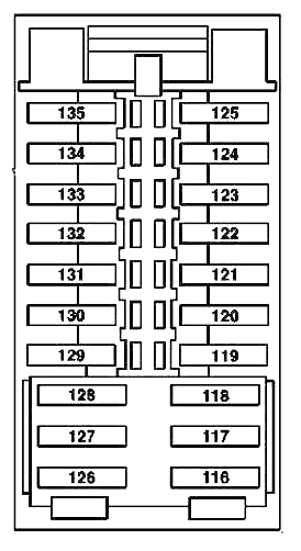
Appointment
| 116 | 30A Driver’s seat control unit (until 05/31/09) |
| 117 | 15A Control unit for adaptive damping system (until 05/31/09) |
| 118 | Reserve |
| 119 | 7,,5A Rear fan motor (until 05/31/09) |
| AMG Performance Media control unit (up to 1.6.12) | |
| 120 | Reserve |
| 121 | Reserve |
| 122 | Reserve |
| 123 | 10A Steering column electronic module control unit |
| 124 | Reserve |
| 125 | Reserve |
| 126 | 30A Front passenger seat control unit (up to 05/31/09) |
| 127 | Reserve |
| 128 | Reserve |
| 129 | 20A Oil cooler fan motor relay (engine 156; before 05/31/09) |
| 130 | Reserve |
| 131 | Reserve |
| 132 | Reserve |
| 133 | Reserve |
| 134 | Reserve |
| 135 | Reserve |
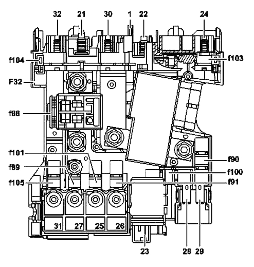
Engine compartment
Fuse and relay box
The main fuse and relay box under the hood is located on the left side.

Diagram

Decoding
| 1 | 25A Блок управления электронной системой стабилизации движения ESP |
| 2 | 30A Блок управления передней левой двери |
| 3 | 30A Блок управления передней двери справа (до 31.3.10 г.) |
| 4 | 7,5A Блок управления топливного насоса (бензиновые двигатели) |
| Fuel pump control unit on the left (engine 156) | |
| Right fuel pump control unit (engine 156) | |
| Condensation sensor in the fuel filter with heating element (engines 642, 651) | |
| Condensation sensor control unit in the fuel filter with a heating element (engines 651 (up to 31.5.10), 646) | |
| 20A Headlight control unit (from 1.3.11) | |
| 5 | 7.5A SAM control unit with fuse and relay module in the rear |
| Relay for the circulation circuit of the coolant of the rear axle gearbox (engine 156 from 1.7.11) | |
| Outdoor lighting switch (from 1.12.09) | |
| 6 | 10A CDI control unit (diesel engines) |
| ME control unit (petrol engines) | |
| 7 | 20A Starter |
| 8 | 7.5A Passenger restraint system control unit |
| 9 | 15A Socket in glove box |
| 10 | 30A Wiper motor |
| 11 | 7.5A Audio/COMAND Display |
| Audio control panel /COMAND | |
| Holder for navigation module | |
| 12 | 7.5A Climate control panel |
| Upper block control panel | |
| 13 | 7.5A Steering column electronic module control unit |
| Multifunction camera (since 1.3.11) | |
| 14 | 7.5A Control unit for electronic stabilization system ESP |
| 15 | 7.5A Passenger restraint system control unit |
| Restraint control unit | |
| 16 | 5A Diagnostic socket (until 5/31/09) |
| electr. mobile phone plug connection (until 2008) | |
| Selector lever electronic module control unit (KP 722) | |
| 17 | 30A Panoramic sunroof control module |
| Ceiling control box control box | |
| 18 | 7.5A Switch for exterior lighting (until 2008) |
| Upper block control panel control unit (as of 1.3.11) | |
| Termination of the positive wire of the LIN data bus of the instrument panel air conditioning system (until 28.2.11) | |
| Electrical plug connection for vehicle interior and cable harness for tail light | |
| 19 | 20A Electric steering lock control unit |
| Electronic ignition lock control unit | |
| 20 | 40A ESP control unit |
| 21 | 7.5A Brake signal sensor |
| Glove box light switch | |
| Seat occupied recognition and front passenger seat AKSE | |
| Electric fuse preparation for installation of the Electronic Toll Collection system (Japan) | |
| 22 | 15A Combustion engine fan motor and air conditioner with integrated regulation |
| Electrical plug-in connection for passenger compartment and engine wiring harness | |
| Cable lug electr. circuit terminal 87 M2e (engine 271; South Korea), (engine 272; USA) | |
| ME control unit (engine 271; South Korea) | |
| Regeneration switching valve (engine 271; South Korea), (engine 272; USA) | |
| CDI system control unit (engines 642, 646) | |
| Heating element in crankcase ventilation duct (engine 642) | |
| Cable lug electr. terminal 87 circuits (engine 646) | |
| 23 | 20A Electrical connector for passenger compartment and engine wiring harness |
| SAM control unit with fuse and relay module in the rear (diesel engines) | |
| CDI system control unit (diesel engines up to 2008) | |
| Cable lug electr. terminal 87 circuits (diesel engines up to 2008) | |
| Cable lug electr. circuit terminal 87 M1e (engine 271 until 2008) | |
| Cable lug electr. circuit terminal 87 M1i (engine 272 until 2008) | |
| 24 | 15A Electrical connector for passenger compartment and engine wiring harness |
| Radiator shutter actuator (engine 642) | |
| CDI control unit (engine 646) | |
| Cable lug electr. circuit terminal 87 M1i (engine 272 until 2008) | |
| Cable lug electr. terminal 87 circuits (diesel engines up to 2008) | |
| 25 | 15A ME control unit (engines 156, 271, 272, 274, 276) |
| Lambda probe in front of the catalyst (engine 651) | |
| The control unit for the sound generator of the exhaust system (engine 651) | |
| 26 | 20A Audio module |
| Audio module with Auto-Pilot system | |
| COMAND control module | |
| 27 | 7.5A Electronic ignition lock control unit |
| Electric steering lock control unit (up to 2008) | |
| CDI control unit (diesel engines) | |
| ME control unit (petrol engines) | |
| 28 | 7.5A Instrument cluster |
| 29 | 10A Front right headlight |
| 30 | 10A Front left headlight |
| Electrical plug-in connection for passenger compartment and engine wiring harness (engine 642) | |
| 31A | 15A Left horn |
| Right horn | |
| 31B | 15A Left horn |
| Right horn | |
| 32 | 40A Electric air pump (engines 156, 271, 272) |
| 33 | 10A Control unit for automatic transmission electronic control system (KP 722.6) |
| Control unit for fully integrated automatic transmission control system (KP 722.9) | |
| 34 | 7.5A Fuel pump control unit (engines 274, 276), (engines 271, 272, 651 from 1.6.09), (engine 642 from 1.12.09) |
| 35 | 5A ESP control unit (since 2009) |
| 36 | 7.5A Electrical control module DISTRONIC |
| Electro-hydraulic power steering (since 2009) | |
| Relay | |
| J | Relay terminal 15 |
| K | Relay terminal 15R |
| L | Reserve |
| М | Terminal 50 relay, starter |
| N | Terminal 87 relay, motor |
| O | Horn relay |
| P | Catalyst Purge Relay |
| Q | Oil cooler fan motor relay |
| R | Terminal 87 relay, running gear |
Power fuse box
Installed on the right side, next to the rack.

Type 1
Diagram
Allocation
| 88 | Pyrofuse: |
| Generator | |
| Starter | |
| 88 | 400A Generator (until 2009) |
| 89 | 125A Front SAM control box with fuse and relay module |
| 90 | 40A SAM control unit with fuse and relay module in the rear |
| 91 | 80A Combustion engine fan motor and integrated air conditioning |
| 100 | 40A Fan regulator |
| Air conditioning box (until 2009) | |
| 101 | 60A Front SAM control box with fuse and relay module |
| Fuse holder, rear left door control unit (UK) | |
| Fuse Holder, Rear Right Door Control Module (UK) | |
| 102 | Reserve |
| 103 | 150A Electric auxiliary heater (diesel engines) |
| Fuse holder, rear left door control unit (UK) | |
| Fuse Holder, Rear Right Door Control Module (UK) | |
| 104 | 70A Interior fuse box |
| 105 | 100A Front SAM control box with fuse and relay module |
| 106 | 150A SAM control unit with fuse and relay module in the rear |
| 107 | Reserve |
| 108 | Reserve |
| 109 | Reserve |
| 110 | Reserve |
Type 2
Diagram for models without “ECO Start-Stop”

Diagram for models with “ECO Start-Stop”
 Appointment
| 150 | 400A Igniter 88 (without “ECO Start-Stop”) |
| 200A Generator | |
| Starter | |
| 151 | 100A Combustion engine fan motor and air conditioner with built-in regulation |
| 152 | 150A Front SAM control box with fuse and relay module |
| 153 | 60A Front SAM control unit with fuse and relay module (vehicles with “ECO Start-Stop”) |
| 154 | 60A Front SAM control unit with fuse and relay module (without “ECO Start-Stop”) |
| 150A Electric auxiliary heater (vehicles with “ECO Start-Stop”) | |
| 155 | Reserve |
| 156 | 150A Additional electric heater (without “ECO Start-Stop”) |
| 100A Front SAM control unit with fuse and relay module (vehicles with “ECO Start-Stop”) | |
| 157 | 100A Electro-hydraulic power steering |
| Electric power steering control unit | |
| 158 | 50A Fan regulator (without “ECO Start-Stop”) |
| 150A SAM control unit with fuse and relay module in the rear (vehicles with “ECO Start-Stop”) | |
| 159 | 50A Multifunction control unit for special vehicle (without “ECO Start-Stop”) |
| 200A Additional battery relay (vehicles with “ECO Start-Stop”) | |
| 160 | 60A Interior fuse box (without “ECO Start-Stop”) |
| 50A Fan regulator (vehicles with “ECO Start-Stop”) | |
| 161 | 100A Front SAM control unit with fuse and relay module (without “ECO Start-Stop”) |
| 50A Multifunction control unit for special vehicle (vehicles with “ECO Start-Stop”) | |
| 162 | 60A Interior fuse box (vehicles with “ECO Start-Stop”) |
| 163 | 150A SAM control unit with fuse and relay module in the rear (without “ECO Start-Stop”) |
| 164 | 80A SAM control unit with fuse and relay module in the rear (without “ECO Start-Stop”) |
Luggage compartment
Fuse and relay box
Installed on the right side behind the side protection.

Diagram

Decoding
| 37 | 7,5A Solenoid coil NECK-PRO driver’s seat headrest |
| 5A Solenoid coil NECK-PRO front passenger seat headrest | |
| 38 | 15A Tailgate wiper motor |
| 39 | 30A Left rear door control unit (until 31.3.10) |
| 40 | Reserve |
| 41 | 30A Right rear door control unit (until 31.3.10) |
| Right front door control unit (from 1.4.10) | |
| 42 | 25A Fuel pump control unit (engine 642 from 12/1/09), (engine 651 from 1/6/09) |
| 20A Fuel pump (646 engine) (642 engine from 11/30/09), (651 engine from 5/31/09) | |
| 20A Before MY 2008: | |
| Fuel pump control unit (petrol engines) | |
| Fuel pump (diesel engines) | |
| 43 | 5A Rear blower motor (from 1.6.09) |
| 44 | 30A Front right seat adjustment switch box |
| Switch for partially electric adjustment of the front passenger seat | |
| 45 | 30A Front left seat adjustment switch box |
| Driver’s seat partially electric adjustment switch | |
| 46 | 7.5A Rear window FM antenna booster |
| Antenna amplifier FM 2 and DAB | |
| alarm siren | |
| Interior protection and towing protection control unit | |
| Antenna amplifier 1 on the rear window | |
| Antenna amplifier TV 1 and DAB antenna band III | |
| Antenna amplifier TV 2 and KEYLESS-GO | |
| Antenna Amplifier KEYLESS-GO | |
| 47 | Reserve |
| 48 | Reserve |
| 49 | 40A Heated rear window |
| 50 | 50A Front right seat belt reversible pretensioner |
| 51 | 50A Front left seat belt reversible pretensioner |
| 52 | Reserve |
| 53 | 15/30A Trailer recognition control unit |
| 54 | 7.5A Trailer recognition control unit (until 5/31/09) |
| 15A Trailer recognition control unit | |
| 5A Group of switches for adjusting the lumbar support and side bolsters of the driver’s seat (since 2009) | |
| Group of switches for adjusting the lumbar support and side bolsters of the front passenger seat (since 2009) | |
| AMG valve block, front passenger seat (since 2009) | |
| Driver’s seat AMG valve block (since 2009) | |
| 55 | 5A AdBlue® control unit (since 2009) |
| 56 | 15A Trailer recognition control unit |
| Trailer socket (since 2009) | |
| 5A Group of switches for adjusting the lumbar support and side bolsters of the driver’s seat (since 2009) | |
| Group of switches for adjusting the lumbar support and side bolsters of the front passenger seat (since 2009) | |
| AMG valve block, front passenger seat (since 2009) | |
| Driver’s seat AMG valve block (since 2009) | |
| 57 | 20A Trailer recognition control unit |
| 58 | 20/30A Trailer recognition control unit |
| 59 | 5A Parking assistance control unit (since 2009) |
| DISTRONIC sensor (DTR) in the front bumper on the left (since 2009) | |
| DISTRONIC sensor (DTR) in the front bumper on the right (since 2009) | |
| Intelligent radar sensor in the left rear bumper (since 2009) | |
| Intelligent radar sensor in the right rear bumper (since 2009) | |
| 7.5A PARKTRONIC control unit (until 2009) | |
| Radar sensors control unit (until 2009) | |
| 60 | 7.5A Air pump for multi-contour seat (since 2009) |
| 61 | 40A Tailgate Actuator Control Module |
| 62 | 30A Driver’s seat control unit (from 1.6.09) |
| 63 | 30A Front passenger seat control unit (from 1.6.09) |
| 64 | 25A AC/DC converter control unit (since 2009) |
| 65 | 15A Control unit for adaptive damping system (from 1.6.09) |
| Steering column electronic module control unit (since 2009) | |
| 66 | 7.5A Gearbox oil circulation pump relay (from 1.6.12) |
| 67 | 30/40A Speaker amplifier control unit |
| 68 | Reserve |
| 69 | 20A Rear sub boofer amplifier (since 2009) |
| 70 | 5A Tire pressure monitoring control unit |
| 71 | 15A Cigarette lighter with front ashtray illumination |
| Saloon outlet front | |
| 72 | 15A Socket in trunk |
| Socket 115 V | |
| 73 | 7.5A Diagnostic socket (since 1.6.09) |
| Driving modes control unit (engine 156 from 1.7.11) | |
| Remote radio control receiver for auxiliary heater (since 2009) | |
| 74 | 15A KEYLESS-GO system control unit |
| 75 | 20A Auxiliary heater heater (since 2009) |
| 76 | 15A Interior socket |
| 77 | 7.5A Passenger weight system (WSS) control unit |
| 78 | 7.5A Front left seat ventilation fan control (since 1.3.11) |
| Front right seat ventilation fan regulator (since 1.3.11) | |
| 79 | 7.5A Radar sensors control unit (until 2009) |
| 80 | 5A Control unit for video sensors and radar sensors (since 2009) |
| Parking assistance control unit (from 1.6.12) | |
| 81 | 5/7.5A Multimedia interface control unit |
| 82 | 5A UMTS mobile communication equalizer (since 2009) |
| TV tuner control unit (until 5/31/09; Japan) | |
| 83 | 7.5A Electronic Toll Collection control unit (up to 28.2.11; Japan) |
| Emergency call system control unit | |
| Rear left display (since 2009) | |
| Rear display on the right (since 2009) | |
| Rear view camera electronics (since 1.6.12; Japan) | |
| 84 | 7.5A Satellite Digital Audio Radio (SDAR) control unit |
| SDAR Control Unit/High Definition Tuner (from 1.6.09 to 31.5.10) | |
| Digital audio broadcasting control unit | |
| Rear view camera power supply module (until 5/31/12) | |
| Rear view camera control unit (until 5/31/12) | |
| Rear view camera electronics (since 1.6.12) | |
| Rear view camera (since 1.6.12) | |
| 360° camera control unit | |
| 85 | 7.5A TV tuner control unit (until 5/31/09; Japan) |
| Digital TV tuner (from 1.6.09; Japan) | |
| 86 | 7.5A DVD player (since 2009) |
| 87 | 7.5A Emergency call system control unit |
| 88 | 15A Servo drive module for automatic transmission DIRECT SELECT (KP 722) (from 1.6.09) |
| 89 | 20A Trailer recognition control unit (from 1.6.09) |
| Oil cooler fan motor relay (engine 156; from 1.6.09) | |
| Relay for the coolant circulation circuit of the rear axle gearbox (from 1.6.09) | |
| 90 | 40A AdBlue® fuse box (from 1.6.09) |
| AdBlue® supply relay (from 1.6.09) | |
| 91 | Reserve (since 1.6.09) |
| 92 | Reserve (since 1.6.09) |
| Relay | |
| A | Relay terminal 15 |
| B | Relay terminal 15R |
| C | Heated rear window relay |
| D | Fuel pump relay (diesel engines) |
| E | Tailgate Wiper Relay |
| F | Seat adjustment relay |
| G | Relay terminal 15R |
Fuses with numbers 71, 72 and 76 are responsible for the operation of the cigarette lighters.
Power fuse box
Another high power fuse box is attached to the positive terminal on the battery in trunk.
Diagram

Assignment
| 111 | 60A Front SAM control box with fuse and relay module |
| 112 | 80A Multi-function control unit for special vehicle |
| 113 | 40A Fuel pump control unit, left (engine 156) |
| Right fuel pump control unit (engine 156) | |
| 114 | Reserve |
| 115 | 100A Multi function control unit for special vehicle |
On our channel we also prepared a video on this publication. Watch the video and don’t forget to subscribe to the channel!
Found a mistake or have something to add – write in the comments.
My name is Kennedy Mmolotsane from Johannesburg South Africa I am driving a Mercedes Benz w204 C250 C class Please I cont. locate boot or trunk fuse or relay. Please help me guys.
Good app Mersedes Dayagrm black & Wait no good please Colar
Hello, I am Kgoshi from Johannesburg, South Africa, i have a mercedes benz C-Class 2014 C180, it jerkes when doing change downs, 3-2-1 0r 2-1 please help