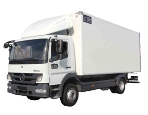
The 1st generation Mercedes-Benz Atego was produced in 1998, 1999, 2000, 2001, 2002, 2003 and 2004. The most popular Mercedes Atego 815 and Mercedes Atego 1223. In this publication you will find a description of the fuses and relays Mercedes Atego 1 with box diagram and its location. Select the cigarette lighter fuse. This material will also be useful to owners of Mercedes Vario, because. they have similar patterns.

The diagram do not fit or the wrong generation? Check this material.
Fuse and relay box
The main fuse and relay box is located at the bottom of the instrument panel on the passenger side behind a protective cover.

Check the actual purpose of the elements in the box with your diagram on the back of the block cover, it may differ from that presented in this publication.
Diagram

Main section
Assignment
Fuses
- F1 – 10A Cabin lighting, diagnostic system, radio terminal 30 or 15A + tail lift KI.30
- F2 – 10A Fog lights
- F3 – 10A terminal 15, other
- F4 – 10A Tachograph, LSVA (heavy duty charges)/Hazards, Instrument cluster terminal 30
- F5 – 10A Right turn signal
- F6 – 10A ABS/BS Terminal 15
- F7 – 25A ABS/BS Terminal 30
- F8 – 10A Dipped beam terminal 30
- F9 – 10A Tachograph, LSVA (Heavy Duty Charges), ZV, Electric Heated Windshield, Distributor Terminal 15
- F10 – 10A Cigarette lighter
- F11 – 10A Low beam headlights
- F12 – 10A Diagnostic socket, mirror heating/adjustment, horn, air conditioning terminal 15
- F13 – 10A Left turn signal
- F14 – 15A Heater fan
- F15 – 10A Illumination of buttons and instruments terminal 58
- F16 – 10A Contour lighting left
- F17 – 10A Main beam right
- F18 – 10A Radio terminal 15R
- F19 – 10A Contour lighting right
- F20 – 10A Main beam left
- F21 – 10A Reversing lights, instrument panel terminal 15
The number 10 fuse is responsible for the cigarette lighter.
Relay
- K1 – Ignition
- K2 – Stop signals
- K3 – Heater
Additional sections
A1
- F1 – 15A Differential lock, NR system, distributor – terminal 30
- F2 – 20A Seat heating
- F3 – 20A Driver window regulator
- F4 – 10A Seats with air suspension terminal 15
- F5 – 10A power take-off, sunroof, EDW (general alarm), tail lift
- F6 – 10A Programmable special module, maintenance system terminal 15
- F7 – 10A ADR (ADR), automatic transmission, tail lift terminal 15
- F8 – 10A Airbag
- F9 – 10A Additional lights
A2
- F1 – 10A Radio, telephone, diagnostic block terminal 30, 12 volts or 15A + navigator terminal 30
- F2 – 10A 12 volt voltage transformer
- F3 – 10A Body lighting, retarder
- F4 – 10A Compressed air dryer, portable lamp, handbrake
- F5 – 15A Voltage transformer input
- F6 – 20A Trailer socket, 15-pin 24V
- F7 – 15A Programmable special module, terminal 30
- F8 – 15A Passenger window regulator
- F9 – 10A Trailer ABS, terminal 15
A3
- F1 – 25A Trailer ABS, terminal 30
- F2 – 25A Heated windshield, oil level sensor
- F3 – 10A automatic transmission, auxiliary heater, NR system
- F4 – 20A Autonomous heater
- F5 – 15A Distributor terminal +D
- F6 – 15A Rotating beacon, headlamp cleaner, working headlight
- F7 – 15A Additional turn signal module
- F8 – 25A Preheating, sunroof, central locking
- F9 – 10A Air suspension seat terminal 30
Relay
- K1 – Additional ignition relay
- K2 – Dehumidifier
- K3 – Trailer ABS relay
- K4 – Headlight cleaning system
- K5 – Automatic transmission oil cooling system
- K6 – Oil cooler pump
- K7 – Seat belt pretensioner
- K8 – Heated windshield
That’s all, if you have something to add – write in the comments.
 FuseAndRelay.com
The engine check light is on after touching the fuses what can be the problem