Ford EcoSport has been produced to date in 2 generations since 2003. The first one was sold exclusively in Latin America. The second one is supplied all over the world and was produced in 2012, 2013, 2014, 2015, 2016, 2017, 2018, 2019, 2020, 2021. During this period of time, it was updated once. In our material you will find information designation the fuse boxes and relays for the second generation Ford Ecosport, boxes diagrams and their photos. Note the cigarette lighter fuse.

The model was assembled at factories in Russia, Romania, China, India and other countries, so there is no one general description of fuses and relays. The general arrangement of the boxes is the same, but their design and the purpose of the circuit elements may differ. In case of difficulty, contact your dealer.
Passenger compartment
Fuse box is located behind the glove compartment. To access the fuse box, follow these steps:
- Open the glove box and take out the contents
- Remove the four screws and then remove the shelf in the glove compartment
- Unfasten the side trim
- Remove the glove box assembly

Photo for example

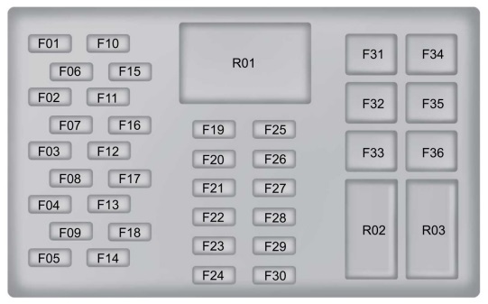
Diagram

Assignment
| F1 | 7.5A Clutch of the air conditioning compressor. Rain sensor module. Auto dimming interior mirror. |
| F2 | 10A Stop lights. |
| F3 | 7.5A Reversing lights. |
| F4 | 7.5A Headlight range correction. |
| F5 | 20A Windshield wiper. |
| F6 | 15A Rear window wiper. |
| F7 | 15A Windshield washer pump. Rear window washer pump |
| F8 | 15A Heated driver’s seat. |
| F9 | 15A Heated passenger seat. |
| F10 | 15A Ignition lock (switch) Ignition switch with a push button. Keyless entry accessory relay. |
| F11 | 3A Instrument panel |
| F12 | 15A Data connector. |
| F13 | 7.5A Microclimate control system – manual air conditioner. Electronic automatic climate control. Alarm sensors. Remote keyless entry receiver. Audio unit control panel. Resetting the front controls display interface module. |
| F14 | 15A Audio system. SYNC module. GPS. |
| F15 | 3A Power folding mirrors. Front windows with glass window regulator. |
| F16 | 20A Remote keyless entry. |
| F17 | 20A Remote keyless entry. |
| F18 | Not used. |
| F19 | 7.5A Instrument panel |
| F20 | Not used. |
| F21 | 3A Passenger airbag deactivation warning light |
| F22 | 7.5A Heated exterior mirrors. |
| F23 | Not used. |
| F24 | Not used. |
| F25 | 7.5A Air conditioning control module. Blower fan. Front fog lights. Cylinder block heater. |
| F26 | 3A Airbag control module. |
| F27 | 10A Parking aid control button. Body systems control unit. Passive anti-theft system. Anti-lock braking system. Ignition lock (switch). Dashboard. Electric power steering. Windshield washer pump. Rear window washer pump |
| F28 | 7.5A Accelerator pedal. High pressure fuel pump. Powertrain control module. Transmission control module. |
| F29 | Not used. |
| F30 | Not used. |
| F31 | 20A Cigarette lighter fuse. Front auxiliary power outlets. |
| F32 | 20A Rear auxiliary power outlets. |
| F33 | Not used. |
| F34 | 30A Front windows with glass lifters. |
| F35 | 30A Rear windows with electric glass. |
| F36 | Not used. |
The fuse number 31, 20A, is responsible for the cigarette lighter.
Relay
- R01 – Ignition
- R02 – Ignition switch with a push button
- R03 – Accessory for the keyless entry system.
Engine compartment
Mounting boxes
The main box with fuses and relays in the engine compartment is located on the left side next to the neck of the washer fluid barrel and is covered with a protective cover.

The photo

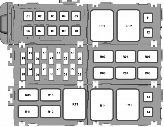
Diagram

Designation
| 1 | 60A Engine compartment fuse box |
| 2 | 40A Anti-lock braking system |
| 3 | 60A Engine compartment fuse box. Powertrain control module |
| 4 | 40A Electric blower fan |
| 5 | 60A Passenger compartment fuse box |
| 6 | 30A Central locking system. Anti-theft alarm |
| 7 | 60A Ignition relay, Passenger compartment fuse box |
| 8 | 30A Starter |
| 9 | 60A High speed cooling fan, Under-hood fuse box. |
| 10 | 30/40 / 60А Transmission control module. Glow plugs. Low speed cooling fan – 1.0L EcoBoost. |
| 11 | 30A Heated windshield (left side) |
| 12 | 30A Heated windshield (right side) |
| 13 | 30A Low Speed Cooling Fan – 1.5L Duratec-16V Ti-VCT and 1.5L Duratorq-TDCi |
| 14 | 30A Transmission control module |
| 15 | 15A Battery discharge prevention system. Front fog lights High beam. Interior lighting. Dipped beam, right side. Passenger airbag deactivation warning light |
| 16 | 15A Dipped beam, left side. Parking lights. Rear fog lamp. Daytime lighting equipment. |
| 17 | 15A High beam |
| 18 | 20A Sound signal |
| 19 | 20A Electronic pump |
| 20 | 7.5A Transmission control module. Powertrain control module |
| 21 | 20A Relay for fuel pump and fuel injectors |
| 22 | 15A Front fog lights High beam. Interior lighting. Direction indicators |
| 23 | 10 / 15A Sound signal for turning on the emergency battery power supply. Anti-theft alarm. Horn relay |
| 24 | 20A Heated rear window. Heated exterior mirrors |
| 25 | Air conditioning relay. Air conditioning relay – 1.0L EcoBoost. |
| 26 | 20a Anti-lock braking system with electronic stability control |
| 27 | 15A Front fog lights |
| 28 | 10A Water pump |
| 29 | 15 / 20A Ignition coil |
| 30 | 15A High speed and low speed cooling fan relay. Powertrain control module. Purging valve of the charcoal filter for the fuel vapor control system. |
| 31 | 15A Cold start solenoid valve. Heated Oxygen Sensor 20A Powertrain Control Module – 1.5L Duratorq-TDCi. |
| 32 | Not used. |
Relay
| R1 | High speed cooling fan |
| R2 | Glow plugs |
| R3 | Front fog lights, Rear fog lights |
| R4 | Fuel Pump – 1.5L Duratorq-TDCi |
| R5 | Reversing lights |
| R6 | High beam |
| R7 | Air conditioning control module |
| R8 | Sound signal |
| R9 | Low speed cooling fan |
| R10 | Starter |
| R11 | Fuel Pump – 1.0L EcoBoost and 1.5L Duratec-16V Ti-VCT. Diesel Fuel Heater – 1.5L Duratorq-TDCi. |
| R12 | Blower fan |
| R13 | Powertrain control module |
| R14 | Cylinder block heater |
| R15 | Cylinder block heater |
Battery box
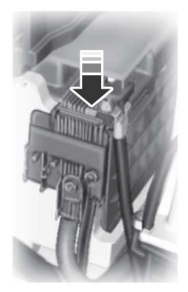
It is located on the positive terminal of the battery, and consists of high power fuse links.

Example

Diagram

Assignment
| F1 | 450A Starter |
| F2 | 60A Electric power steering. |
| F3 | 200A Engine compartment fuse box. |
| F4 | 70A Cylinder block heater. |
| F5 | 50A Cylinder block heater. |
| F6 | 30A Battery monitoring system. |
In some models, in the places where the cooling fans are connected, it is possible to install separate thermal fuses.
That’s all, and if you have something to add, write in the comments.
 FuseAndRelay.com
Very nice guide but I could not find the location of the Turn Signal Relay.
YUNG SA fORD ambiente SOCKET