The Citroen Jumpy commercial vehicle is marketed in both cargo and passenger versions. At the moment, the 3rd generation of this series is being produced. Our information with the description of Citroen Jumpy fuses is relevant for cars produced in 2007, 2008, 2009, 2010, 2011, 2012, 2013, 2014, 2015, 2016, 2017, 2018.

As provided Jumpy three main boxes with fuses:
- in the dashboard on the right side
- in the cabin
- in the engine compartment.
If equipped with your car, an additional fuse box is installed to protect the electrical circuits of the trailer, as well as to connect the wiring harnesses on models with a modified body and platforms with a cab. The box is located on the right side behind the cargo bulkhead.
Contents
Passenger compartment
Fuse box
To access, lower the glove box and pull firmly on it.

Location

Photo

Diagram

Assignment
- 15A Rear window cleaner
- Free
- 5A Airbag ECU
- 10A Steering wheel position sensor, diagnostic socket, ESP sensor, manual climate control, clutch sensor, headlight range control, diesel particulate filter additive pump
- 30A Power mirrors, front right door window motor
- 30A Power supply for front door windows
- 5A Lights and glove box lamp
- 20A Multifunction display, burglar alarm siren, car radio, CD changer, radiotelephone, trailer switching unit (optional), ECU for platform modification with cab
- 10A Socket in the cargo compartment
- 30A Rear suspension height adjuster, steering column switch block, instrument cluster
- 15A Diagnostic connector, ignition switch
- 15A Wireless Hands-Free, Airbag ECU, Parking Assist ECU
- 5A Engine ECU, trailer switching unit
- 15A Rain sensor, interior ventilation, climate control, instrument cluster
- 30A Locking / unlocking / super locking doors
- Free
- 40A Heated rear window, mirror heaters
- 10A Heaters of mirrors
Block next to the battery
To access, simply remove the battery cover.
Diagram
Designation of elements
| No. | Protected chain |
| 1 | 30A Seat heaters |
| 2 | 20A 12V socket in the third row of seats (minibus) or not used (van) |
| 3 | 40 / 50A Trailer switching unit (optional equipment), ECU for platform modification with cab |
| 4 | Not involved |
| 36 | 15A Swing door locks |
| 37 | 10A Swing door locks |
| 38 | 20A Rear swing door wiper |
| 39 | Interior ventilation (minibus) or not involved (van) |
| 40 | 5A Folding mirrors |
Engine compartment
Move the washer reservoir bracket to the side for easier access to the box.

Photo

Diagram

Decoding
- Engine ECU, components, power supply and air supply systems, cooling fan 20A
- Sound signal 15A
- Windscreen and rear window washer pump 10A
- Headlight washer pump 20A
- Components of the fuel supply system 15A
- Power steering, second brake pedal sensor 10A
- Brake system (ABS / ESP) 10A
- Starter switch 20A
- First brake pedal sensor 10A
- Components of the power supply and air supply system, components of the toxicity reduction system 30A
- Cabin ventilation 40A
- Windshield cleaner 30A
- Intelligent switching unit 40A
- Not used 30A
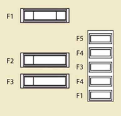
Additional fuse box
It refers to a trailer, platform with a cab and other body modifications and is located behind the cargo bulkhead on the right.
Diagram

1 – 15A Free
2 – 15A Relay for ignition switch and optional alternator
3 – 15A 12V power supply for trailer electrical circuit
4 – 15A Energized circuit for use with modifications
5 – 10A Hazard lights
Check out our YouTube video for more on this topic. Don’t forget to subscribe!
Enjoy the video and drive safe!
No info on relays here. I want to know where the driver’s door window motor relay is.