Citroen C4 Picasso is a compact MPV, which was produced in five-seater and seven-seater (C4 Grand Picasso ) modifications in 2006, 2007 2008, 2009, 2010, 2011, 2012, 2013 (1st generation) with both gasoline and diesel engines. After that, the model was updated and in 2014, 2015, 2016, 2017, 2018, 2019, 2020, 2021, the 2nd generation Citroen C4 Picasso was assembled. In this material you will find a designation of fuses and relays Citroen C4 Picasso and C4 Grand Picasso with box diagrams and their locations for two generations. Note the cigarette lighter fuses.

The design of the box and the purpose of the elements in them may differ from the one presented and depend on the year of manufacture and the level of equipment.
Contents
Passenger compartment
Main box
It is installed under the dashboard on the left-hand side behind a protective cover (BSI1).
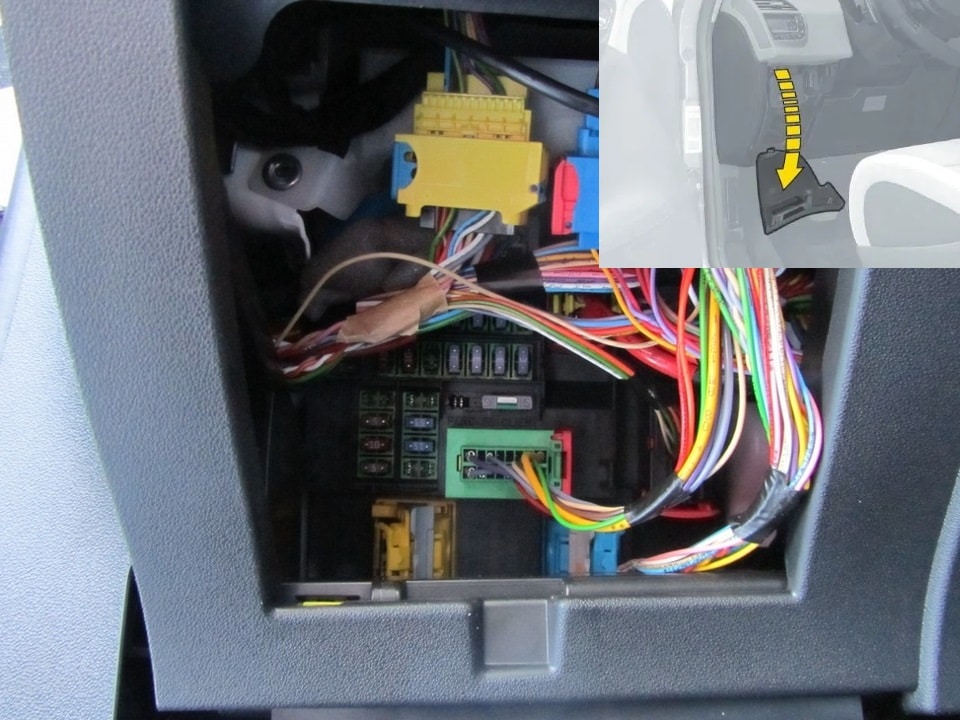
Type 1
Photo for example
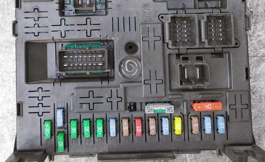
Diargram

Assignment
F1 | 15A Rear window wiper |
F2 | 30A Central locking |
F3 | 5A SRS |
F4 | 10A Multimedia Equipment Self Dimming Rearview Mirror Particulate Filter Diagnostic Connector Air Conditioning Headlight Regulator |
F5 | 30A Front glass lifts, electronic panel on the front door, panoramic sunroof |
F6 | 30A Electric rear window lifters |
F7 | 5A Interior lights, cooled glove box, car radio |
F8 | 20A Multi function display, car radio, steering wheel control unit, multimedia equipment, tire pressure drop detection system, burglar alarm, trailer |
F9 | 30A Cigarette lighter , multimedia equipment, front 12V socket, portable lamp in trunk, car radio |
F10 | 15A Suspension control unit |
F11 | 15A Brake pedal contactor, ignition switch |
F12 | 15A Parking aid, automatic wiper and lights, passenger seat power supply, lane crossing warning system, hi-fi amplifier, trailer |
F13 | 5A Engine switch module (BSM), driver’s seat power supply |
F14 | 15A Air conditioning, Bluetooth hands-free headset, automatic transmission selector, airbags, instrument panel |
F15 | 30A Central locking |
F17 | 40A Heated rear window |
| F29 | 20A Heated seats |
| F30 | – |
| F31 | 40A Trailer switch box |
| F32 | 15A Rear 12V cigarette lighter socket |
| F33 | 5A Parking aid, automatic wiper and lights, passenger seat power, lane crossing warning, hi-fi amplifier |
| F34 | 5A Trailer electrical connector |
| F35 | – |
| F36 | 20A Audio amplifier |
| F37 | 10A Air conditioning, lights |
| F38 | 30A Driver’s seat power supply |
| F39 | 5A Central locking or Fuel filler flap |
| F40 | 30A Power supply, passenger seat, panoramic sunroof |
The fuses numbered 9 and 32 are responsible for the operation of the cigarette lighter.
Type 2
Diagram
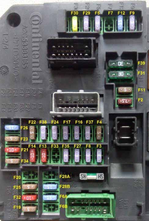
Designation
F2 7.5A Diagnostic connector.
F3 3A Anti-theft device or START / STOP button.
F4 5A Reader for remote control key.
F5 3A Remote control key.
F6A-F6B 15A Touchscreen display, audio and navigation system, CD player, USB and additional connectors.
F7 15A Hands-free start assist electronics
F8 3A Burglar alarm siren, alarm processor
F9 3A Steering wheel switch box
F11 5A Stability calculator, common alarm switch box, electronic key scanner
F12 15A Double contactor brake pedal
F13 10A Front cigarette lighter
F14 10A Rear cigarette lighter.
F16 3A Individual lights, glove box lighting.
F17 3A Sun visor illumination, individual lamps.
F19 5A Instrument panel.
F20 5A Electronically controlled manual transmission gear selector.
F21 10A Car radio and air conditioning control.
F22 5A Displays, parking sensors.
F23 5A Engine compartment fuse module.
F24 3A Rain and light sensor.
F25 15A Block of airbags and pyrotechnic tensioners.
F26 15A
F27 3A Double brake pedal contactor.
F28A-F28B 15A Car radio, autoradio (optional).
F29 3A Steering column switch.
F30 20A Rear window wiper.
F31 30A Central locking, front and rear external and internal locks.
F32 10A Power supply for rear view camera in C4L China. (16V NE 13pin output), audio amplifier.
F33 3A Driver’s seat memory unit.
F34 5A Power steering relay.
F35 3A
F37 3A Driver’s door wiper / rearview mirror control – Electro chrome interior rearview mirror
F38 3A Headlight range control switch – Electro chrome rearview mirror.
F39 30A
In this version, fuses 13 and 14 are responsible for the cigarette lighter.
Type 3

Diagram

Assignment
- F8 5A Steering wheel control unit.
- F18 20A Touchscreen display, audio and navigation system, CD player, USB and auxiliary connectors.
- F16 15A Front 12V socket.
- F15 15A 12V socket in trunk.
- F28 5A START / STOP button.
- F30 15A Rear wiper.
- F27 15A Windscreen washer pump, rear window washer pump.
- F26 15A Sound signal.
- F20 5A Airbags.
- F21 5A Instrument panel.
- F19 5A Rain and light sensor.
- F12 5A Remote engine start unit.
- F2 5A Manual headlight range control
Additional boxes
For comfortable access, it will be necessary to remove the lower part of the panel.

The blocks themselves can be attached behind or under the main block.
BFH3

Diagram

Protected components
| F3 | 15A compartment fuse box 5 for taxi version |
| F4 | 15A 12V socket for multimedia equipment |
| F5 | 30A electric motors for rear window lifts |
| F6 | 30A electric motors for front glass lifters |
| F7 | 2A heated seats |
| F8 | 20A air conditioner fan |
| F9 | 30A electric tailgate |
| F10 | 40A left seat belt reel |
| F11 | 5A trailer switching unit |
| F12 | 30A electric driver seat and massage device |
| F13 | 40A right seat belt reel |
| F14 | 30A Reinstalling Handle – Power Passenger Seat – Seat Massage Devices |
| F15 | 25A electric sunroof blinds |
| F16 | 5A multiplex control board glass lifter / door mirror driver’s door |
| F17 | 10A unit of illumination and memory of the position of external rear-view mirrors |
| F18 | 25A audio amplifier |
| F19 | not used |
| F20 | 7.5A electric tailgate |
| F21 | 3A “Hands free” access and start unit |
| F2 | 7.5A electrically heated mirrors |
| F22 | 20A socket 230V |
| F23 | not used |
| R1 | 230V socket |
| R2 | 12V connector |
| R3 | not used |
| F1 | 40A rear window heating |
BFH5

Diagram

Assignment
F1 40 A Heated rear window.
F2 20 A Power mirrors.
F5 30 A Panoramic sunroof
F6 20 A 12 V socket, rear multimedia.
F7 20A socket 230V.
F9 25A Heated seats.
F10 20 A Trailer interface box.
F11 20 A Air conditioner fan.
F12 30 A Power window motors.
For the rear cigarette lighter, circled in red in the photo, fuse number 6 is still responsible, and for models 2013 – 2015 it may be number 9.
Engine compartment
Fuse box
Located on the left side of the engine compartment next to the battery, covered with a protective cover.
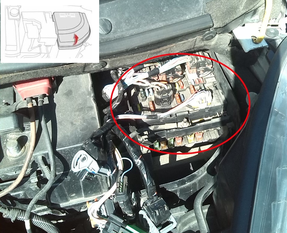
Type 1
Diagram 1
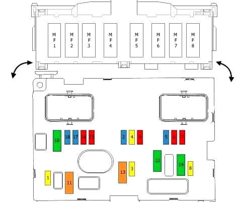
Diagram 2

Assignment
| 1 | 20A Engine management |
| 2 | 15A Buzzer |
| 3 | 10A Windshield / rear window washer pump |
| 4 | 20A Headlight washer pump |
| 5 | 15A fuel pump |
| 6 | 10A Adaptive bi-xenon headlights, automatic headlamp leveling, clutch pedal contactor, protective switching unit (WCP). |
| 7 | 10A Automatic transmission, coolant level sensor, power steering. |
| 8 | 15A / 20A Starter |
| 9 | 10A Brake light contactor. |
| 10 | 30A engine management |
| 11 | 40A Rear air fan. |
| 12 | 30A Windshield wiper |
| 13 | 40A Intelligent Switching Unit (BSI). |
| 14 | 30A Boost pressure control solenoid valve, heat exchanger recuperator. |
| 15 | 10A High beam, right headlight |
| 16 | 10A High beam left headlight |
| 17 | 15A Low beam left headlight |
| 18 | 15A Low beam, right headlight |
| 19 | Engine management systems |
| 20 | 15A Engine management |
| 21 | 10A Fuel filter heating 5A Cooling system relay |
| MF1 | 30A ABS |
| MF2 | 30A ABS |
| MF3 | 30A Parking brake control unit |
| MF4 | 80A Pre-starting heating |
| MF5 | 20A Headlight washers |
| MF6 | 50A Air conditioning / heater |
| MF7 | 50A |
| MF8 | 50A Suspension control unit |
MF * – these fuses are located on the side, at the bottom of the unit.
Type 2
Diagram
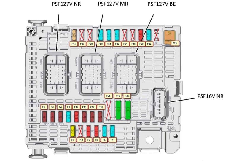
Protected components
F1 15A engine computer – current generation protection unit
F2 5A electric cooling fan control unit
F4 5A centralized voltage maintainer – reversing alternator
F5 15A engine computer
F7 10A engine computer
F8 10A engine computer
F9 30A Electric tailgate
F11 15A protection switching unit – block headlight correction – additive pump
F12 5A APC parking assist computer with city park system – reversing seat belt reel
F13 – not used
F14 25A Front and rear washer pump – A / C compressor
F16 – not used F18 25A Hi fi amplifier
F17 10A Intelligent switching unit (BSI )
F19 30A low / high speed windscreen wiper
F15 5A vehicle spacing assist computer – diagnostic socket – engine coolant level contactor – power steering computer
F20 15A front and rear wiper
pump F21 20A headlight washer pump
F22 15A horns
F23 15A left halogen high beam
F24 15A right halogen high beam
F25 – not used
F26 – not used
F27 5A left headlamp with shutter
F28 5A right headlight with shutter
F29 30A APC starter
F30 30A APC engine calculator
R2 – not used
R3 – not used
R4 – engine computer – power generation protection unit – electric cooling fan control unit – central voltage maintaining device – reversible alternator
R7 – starter
R8 – not used
R9 – not used
R10 – front and rear wiper
pump R11 – headlight washer pump
R12 – sound signaling
R13 – left headlight with curtain
R16 – not used
R17 – right headlight with curtain
R6 – Electric steering lock – Safety switch unit – Headlight range control unit – Additive pump – City park parking aid computer – Reversible seat belt reels – Vehicle interval assistance computer – Diagnostic socket – Engine coolant level contactor – power steering computer – intelligent switch
box
F6 20A engine calculator
F9 10A Electrical anti-theft system
R1 – engine calculator
R5 – engine calculator
R14 – right halogen high beam headlight
R15 – left halogen high beam headlight
F3 5A engine calculator
Main box
Photo – an example of execution

Type 1
Diagram

Assignment
| 1 | – |
| 2 | – |
| 3 | (5A) Battery condition sensor |
| 4 | (5A) Transmission control module (ECM) |
| 5 | (5A / 15A) Diagnostic connector (DLC) |
| 6 | (15A) Transmission control module (ECM) |
| 7 | (5A) ABS ESP control unit |
| 8 | (20A) Rear 12V socket |
| FL9 | (60A) Fuses on BSI (Intelligent Power Distribution Module) |
| FL10 | (80A) Power steering |
| FL11 | (30A) Transmission control module (ECM) |
| FL12 | (60A) Cooling fan motor |
| FL13 | (60A) Fuses on BSI (Intelligent Power Distribution Module) |
| FL14 | (70A) Glow plugs |
| FL15 | (100A) Relay protection relay box 3 |
| FL16 | – |
Type 2
F1 80A fuse switch board
F2 70A fuse switch board
F3 50A ESP computer
F4 15A alarm switch box
F5 40A ESP computer
F6 – not used
F7 – not used
F8 80A power steering relay – power steering computer
F9 125A fuse switch board
F10 60A intelligent switch box (BSI)
F11 40A passenger compartment fuse box 5
F12 60A passenger compartment fuse box 3
F13 60A passenger compartment fuse box 3
F14 – not used
F15 – not used
F16 70A preheating unit
F17 – not used
F18 50A not used
F19 40A
F20 30A reserved for 12V plug-in
F21 5A not used
F23 60A control unit for two-speed electric fan group
F24 40A air conditioner fan
F25 – not used
F26 30A electronic manual transmission computer
F27 80A switching and protection
unit F22 5A status unit battery charge
We have posted a video on our YouTube channel. Watch and subscribe.
That’s all. If you have something to add, write in the comments.
 FuseAndRelay.com
what is a central relay unit and where do I find it?
where is the 2014 CITROEN C4 GRAND PICASSO MK2 PDC PARKING DISTANCE CONTROL MODULE located?
Where do I find the fuse/s for the front side lights?
i cannot find the front side lights / parking lights fuse / relay
My near side head lamp repeatedly goes out and the bulb is intact. Number 17 on Diagram 2 seems to be the relevant fuse, but it does not match with what I can see in my 2017 Gran Picasso C4.
Where am I going wrong?
Where is the park assist module
Location citroen grand passo C4
2017 HELP
Hi where is the electronic handbrake fuse please? Or is it called something else?
Had the electric cable snap on me like most of the cars but still saying handbrake fault some saying might have blown the fuse please help??
Can anyone identify a 10A fuse in the bottom right of a Type 2 fuse box.
In the diagram above there is a 10A in F26 (not used) then a 15A in F22 (horns) then an empty space.
In my fuse box I have nothing in F26, a 15A in F22(horns) and a 10A where they have an empty space.
Tried going through everything and no idea, it does have a live feed going to it