Chevrolet Malibu 6st generation was produced in 2004, 2005, 2006, 2007. In our post you will find a detailed description of the Chevrolet Malibu 6G fuse and relay boxes with diagrams and photographs. We’ll highlight the fuse responsible for the cigarette lighter.

The description of the fuses may differ from the one shown and depend on the year of manufacture and the equipment level of your car.
Location
Passenger compartment
You’ll find the fuse box for the instrument panel on the passenger side panel of the centre console. To access the fuses, just open the fuse panel door from the passenger side by pulling it out.

Diagram

Assignment
| 1 | 15A Body Control Module (Door Locks) |
| 2 | 10A Body Control Module (Interior Lamps) |
| 3 | – |
| 4 | 10A Adjustable Pedals Module, Adjustable Pedals Position Switch |
| 5 | 10A Vehicle Communication Interface Module (VCIM (OnStar)) |
| 6 | 2A Outside Rearview Mirror Switch |
| 7 | 10A Heated Seat Control Module (Driver/Passenger), Heated Seat Switch (Driver/Passenger), Inside Rearview Mirror, Sunroof Control Module |
| 8 | 20A Rear Window Wiper Module |
| 9 | – |
| 10 | 10A Windshield Wiper/Washer Switch |
| 11 | – |
| 12 | 2A Power Steering Control Module |
| 13 | 30A Power Windows |
| 14 | 10A Inflatable Restraint Sensing and Diagnostic Module (SDM) |
| 15 | 2A A/T Shift Lock Control Assembly, Cruise Control On/Off Switch |
| 16 | – |
| 17 | 10A Heating Ventilation Air Conditioning (HVAC) Control Module |
| 18 | – |
| 19 | 20A Heating Ventilation Air Conditioning (HVAC) Blower Switch |
| 20 | 10A Inflatable Restraint Sensing and Diagnostic Module (SDM) |
| 21 | 10A Audio System |
| 22 | 2A Ignition Switch |
| 23 | 10A Data Link Connector (DLC), Heating Ventilation Air Conditioning (HVAC) Control Module |
| 24 | 10A Instrument Panel Cluster, Theft Deterrent Control Module |
| Relay | |
| R1 | Blower Motor |
| Relay (Non-Serviceable) | |
| R2 | Power Door Lock (Lock) |
| R3 | Power Door Lock (Unlock) |
| R4 | Driver Door Lock Actuator (Unlock) |
| R5 | Interior Lamps |
Some relays can be attached to the back side of the block: Accessory (Power Window, Sunroof, Heated Seat, Windshield Wiper/Washer Switch) and Run (Heating Ventilation Air Conditioning).
Luggage compartment
In the luggage compartment, the fuse and relay box is located behind the trim on the left side.

Check the purpose of the block elements with your diagrams on the back of the protective cover.

Diagram
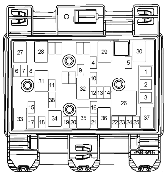
Designation
| 1 | – |
| 2 | 30A Driver Seat Controls |
| 3 | – |
| 4 | Resistor: Door Lock Actuator (Driver) |
| 5 | 10A Evaporative Emission (EVAP) Canister Vent Solenoid Valve |
| 6 | 10A Park Lamps Relay (Body Control Module (BCM), License Lamps, Park/Turn Signal Lamps, Tail Lamps, Tail/Stop and Turn Signal Lamps), Instrument Panel Dimming |
| 7 | – |
| 8 | – |
| 9 | – |
| 10 | 15A Sunroof Control Module |
| 11 | – |
| 12 | 20A Power Outlet (Rear) |
| 13 | – |
| 14 | 15A Heated Seat Controls |
| 15 | – |
| 16 | 7,5A Digital Radio Receiver, Garage Door Opener Transmitter, Remote Control Door Lock Receiver, DVD Player |
| 17 | 10A Back-Up Lamps Relay |
| 18 | – |
| 19 | – |
| 20 | 20A Cigar Lighter, Auxiliary Power Outlet (Console or Front) |
| 21 | – |
| 22 | 10A Trunk Release Relay |
| 23 | 30A Rear Window Defogger |
| 24 | 10A Heated Mirrors |
| 25 | 15A Fuel Pump Relay |
| Relay | |
| 26 | Rear Window Defogger, Heated Mirrors |
| 27 | Park Lamps (Back-Up Lamps, Body Control Module (BCM), Garage Door Opener Transmitter, HVAC Control Module, License Lamps, Park/Turn Signal Lamps, Tail Lamps, Tail/Stop and Turn Signal Lamps) |
| 28 | – |
| 29 | – |
| 30 | – |
| 31 | – |
| 32 | – |
| 33 | Back-Up Lamps, Inside Rearview Mirror |
| 34 | – |
| 35 | – |
| 36 | Trunk Release |
| 37 | Fuel Pump |
| Diode | |
| 38 | Trunk Release |
Engine compartment
Under the hood, the main fuse and relay box is located on the front left, near the battery.

Diagram
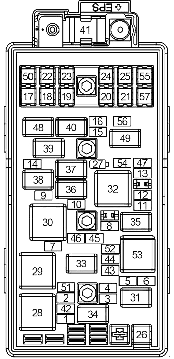 Allocation
| 1 | 10A Air Conditioning Compressor Clutch Relay |
| 2 | 15A 3.9L (LZ9): Engine Control Module (ECM), Throttle Actuator Control (TAC) Module |
| 15A 2.2 (L61): Powertrain Control Module (PCM) | |
| 3 | 15A Ignition Control Module (ICM), Park/Neutral Position (PNP) Switch |
| 4 | 10A 1-2 Shift Solenoid Valve, 2-3 Shift Solenoid Valve, Torque Convertor Clutch Pulse Width Modulation (TCC PWM) Solenoid Valve |
| 5 | 10A Fuel Injectors |
| 6 | 10A Evaporative Emission (EVAP) Canister Purge Solenoid Valve, Heated Oxygen (HO2S) Sensors, Mass Air Flow (MAF)/Intake Air Temperature (IAT) Sensor |
| 7 | 10A Left Headlamp (Low Beam) |
| 8 | 15A Horn Relay |
| 9 | 10A Right Headlamp (Low Beam) |
| 10 | 15A Front Fog Lamp Relay |
| 11 | 10A Left Headlamp (High Beam) |
| 12 | 10A Right Headlamp (High Beam) |
| 13 | 10A 3.9L (LZ9): Engine Control Module (ECM) |
| 10A 2.2 (L61), 3.5L (LX9): Powertrain Control Module (PCM) | |
| 14 | 25A Wiper 1 Relay, Wiper 2 Relay, Windshield Wiper Motor Assembly |
| 15 | 10A ABS (Electronic Brake Control Module (EBCM)) |
| 16 | 10A 3.9L (LZ9): Engine Control Module (ECM) |
| 10A 2.2 (L61), 3.5L (LX9): Powertrain Control Module (PCM) | |
| 17 | 30A Cooling Fan Relay No.1 |
| 18 | 30A Cooling Fan Relay No.2 |
| 19 | 30A Blower Motor Control Module, Blower Motor Relay, “RUN” Relay |
| 20 | 30A Body Control Module (BCM), Fuse (Passenger Compartment): “20”, “21”, “22”, “23”, “24” |
| 21 | 30A Fuse (Passenger Compartment): “12”, “14”, “15” |
| 22 | 60A Fuse (Luggage Compartment): “10”, “14”, “16”, “17”, “20”, “23” |
| 23 | 60A Fuse (Luggage Compartment): “1”, “2”, “5”, “6”, “22”, “25” |
| 24 | 60A ABS (Electronic Brake Control Module (EBCM)) |
| 25 | 50A Body Control Module, Fuse (Passenger Compartment): “1”, “2”, Accessory Relay |
| 26 | 30A Starter Relay |
| 41 | 80A Power Steering Control Module |
| 42 | 10A Transmission Control Module |
| 43 | 15A Ignition Control Module (ICM) |
| 44 | 10A Fuel Injectors |
| 45 | 10A Intake Manifold Tuning (IMT) Valve Solenoid |
| 46 | – |
| 47 | – |
| 50 | – |
| 51 | – |
| 52 | – |
| 54 | – |
| 55 | – |
| 56 | – |
| 57 | – |
| Relay | |
| 28 | Cooling Fan (No.1 (Left)) |
| 29 | Cooling Fan |
| 30 | Cooling Fan (No.2 (Right)) |
| 31 | Starter Motor |
| 32 | Run/Crank (Ignition) |
| 33 | Engine Control Module (ECM) |
| 34 | Air Conditioning Compressor Clutch |
| 35 | Headlamp (High Beam) |
| 36 | Front Fog Lamp |
| 37 | Horn |
| 38 | Headlamp (Low Beam) |
| 39 | Wiper (No.1) |
| 40 | Wiper (No.2 – Windshield Wiper Motor) |
| 48 | – |
| 49 | – |
| 53 | – |
| Diode | |
| 27 | Wiper 1 Relay, Wiper 2 Relay |
On our channel we have also prepared a video on this article, watch and subscribe.
If you have any questions, ask them in the comments.