BMW X6 E71 E72 crossover combined the best features of BMW SUVs (all-wheel drive, high ground clearance, large wheels, high-torque engine) and a coupe (a strong roof slope at the rear of the car). This series was produced in 2008, 2009, 2010, 2011, 2012, 2013 and 2014. After that, the car received a restyling and is produced to this day under the body marking F16. Our publication provides detailed information about the BMW X6 e71 / 72 fuse boxes and relays with their description of the purpose, fuse box diagrams and photo examples of execution. We will also highlight the fuses responsible for the cigarette lighter.

Contents
Passenger compartment
Fuse box is located on the right side, at the feet of the front passenger. For access, we go down under the glove compartment and unscrew the three screws.

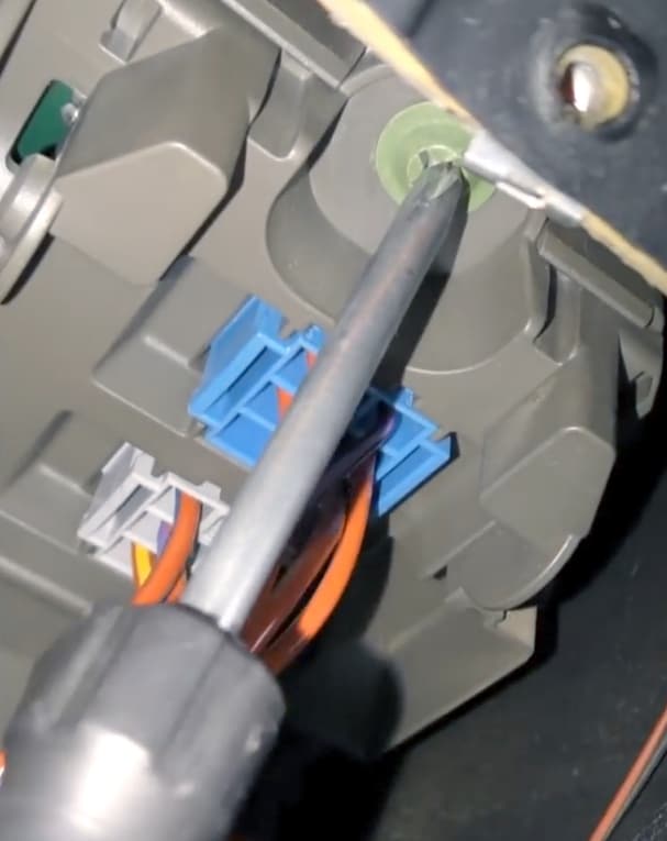
We remove the released cover. Raise our head and in the space that appears on top we find a green screw on the right side.

Unscrewing it – the fuse box will fall to the floor (go down).

It will look something like this.


Diagram

Assignment
| 1 | 20A Steering column adjustment motor, heating and air conditioning |
| 2 | 10A Glove box lock, glove box lighting (10.2009→) |
| 3 | 7.5A Anti-theft siren, tilt sensor |
| 4 | 10A except N55: Engine control unit (DME) |
| 10A N55: Built-in power module | |
| 10A ActiveHybrid: Engine control unit (DME) | |
| 5 | 10A Ceiling console |
| 6 | 10A iDrive joystick, DVD changer, CD changer, video switch |
| 7 | 5A Active Cruise Control, Longitudinal Dynamics Control, Tire Pressure Control (RDC) |
| 8 | 7.5A Vertical dynamics management system (damper satellite front left/right) |
| 9 | 15A Horn relay (horn left/right) |
| 10 | 5A Parking brake, vehicle access system |
| 11 | 20A Auxiliary/additional heater |
| 12 | 10A Switching center in the steering column |
| 13 | 15A Transmission control system |
| 14 | 10A Dynamic Drive Active Suspension System |
| 15 | 10A Gear selector |
| 16 | 10A Driver’s door switch box, driver’s outside mirror, front passenger’s outside mirror |
| 17 | 5A Central information display, heating and air conditioning system (without power steering column), active video signal switch (Japan) |
| 18 | 7.5A Upper display, electronics box fan, fuel tank vent valve (→09.2011), fuel tank vent shut-off valve (→09.2011) |
| 19 | 5A Dynamic Stability Control (DSC), overhead console (without sunroof) |
| 20 | 10A Integrated Chassis Management (ICM), Servotronic (without ICM) |
| 21 | 30A Heated rear window |
| 22 | 5A Left headlight |
| 23 | 40A Footwell module |
| 24 | 40A Active steering system |
| 25 | 5A Right headlight |
| 26 | 30A →08.2008: Headlight washer pump |
| 15A 08.2008→: Headlight washer pump | |
| 27 | 15A →03.2010: Central locking |
| 20A 04.2010→: Central locking | |
| 28 | 15A Central locking |
| 29 | 40A Rear left power window |
| 30 | 30A Central locking |
| 31 | 40A Rear right power window |
| 32 | 40A Air suspension compressor |
| 33 | 30A Footwell module |
| 34 | 30A Footwell module |
| 35 | 30A N63, S63, ActiveHybrid: Lambda probes |
| 36 | 30A N63, ActiveHybrid: VANOS solenoid valve #2 – intake side, VANOS solenoid valve #2 – exhaust side, crankshaft sensor, charge air recirculation valve, recirculation valve #2, hot air mass meter (#1, #2) |
| 37 | – |
| 38 | 30A N57: Load relay SCR |
| 39 | 40A Vehicle access system |
| 40 | 30A Dynamic Stability Control (DSC) |
| 41 | 7.5A N63, S63, ActiveHybrid: Charge air cooler #2 coolant pump, radiator shutter drive |
| 7.5A N54: Teroanemometric secondary air mass meter, radiator shutter drive | |
| 42 | 30A N63, S63, ActiveHybrid: Engine control module (DME), intercooler coolant pump, quantity control valve, wastegate pressure converter (#1, #2) |
| 30A N54: Engine control unit (DME), tank vent valve, crankshaft sensor, quantity control valve, lambda probes (before catalytic converter) | |
| 43 | 30A N63, S63, ActiveHybrid: Intake camshaft position sensor (#1, #2), exhaust camshaft position sensor (#1, #2), oil condition sensor, fuel tank vent valve, programmable thermostat, intercooler coolant pump |
| 30A N54: Lambda probes (after catalytic converter), oil condition sensor | |
| 44 | 30A Front wiper |
| Non-replaceable fuses | |
| 45 | 60A Engine cooling fan motor open relay (fan motor) |
| 46 | 40A Dynamic Stability Control (DSC) |
| 47 | 40A N57, M57US: Fuel heating system |
| 48 | 40A Heater (fan output stage) |
| 49 | – |
| Relay | |
| R1 | Windshield wiper motor relay |
| R2 | Air suspension compressor relay |
| R3 | Rear window wiper relay |
Petrol engines:
N54B30 – 3.0L (xDrive35i)
N55B30 – 3.0l. (xDrive35i)
N63B44 – 4.4l. (xDrive50i, ActiveHybrid X6)
S63B44 – 4.4L (X6M)
Diesel engines:
M57D30TÜ2 – 3.0l. (xDrive30d, xDrive35d)
N57D30OL – 3.0l. (xDrive30d)
N57D30TOP – 3.0l. (xDrive40d)
N57S – 3.0l. (X6 M50d)
Luggage compartment
Fuse and relay box
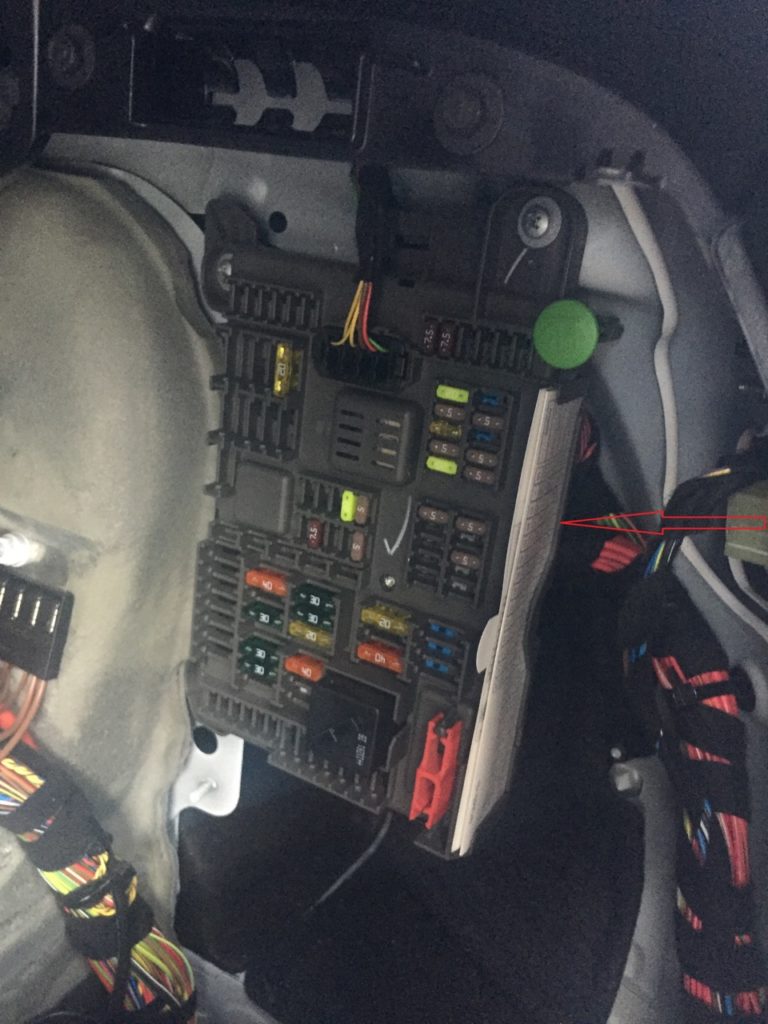
Located on the right-hand side under the casing.

There should also be a brochure with an up-to-date description of the fuses for your vehicle. It is marked with a red arrow in the picture.

Check the purpose of the elements with your information in the brochure.
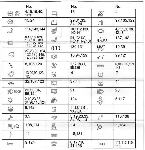
Example of a fuse description table

Dealing with her is easy. For example, fuses 110 and 136 are responsible for the phone, 16 for adjusting the side mirrors, 10, 39 for starting and stopping, etc.
Diagram

Designation
| 91 | 30A Rear right auxiliary electric heater |
| 92 | 25A →03.2011: Transfer box control unit |
| 30A 04.2011→: Transfer case control unit | |
| 93 | 30A Lateral torque distribution to the rear axle (QMVH) |
| 94 | 30A Parking brake control unit |
| 95 | 30A Rear left electric auxiliary heater |
| 96 | 40A Footwell module |
| 97 | 20A →09.2008: Fuel Pump Relay (Without EC Fuel Pump), Fuel Pump Control (EKPS) (With EC Fuel Pump) |
| 98 | 15A Rear fan motor |
| 99 | 40A 03.2007→: Tailgate lift |
| 100 | 20A Rear left seat heating module, terminal 15 of the energy saving relay (without air conditioning in the rear) |
| 101 | 30A Driver seat module, driver seat adjustment switch, driver lumbar support switch |
| 102 | 30A Passenger seat module, passenger seat adjustment switch, passenger lumbar support switch |
| 103 | 30A →09.2009: Audio amplifier |
| 40A 10.2009→: Audio amplifier | |
| 104 | 25A Power hitch |
| 105 | 20A 10.2008→: Fuel Pump Relay (Without EC Fuel Pump), Fuel Pump Control (EKPS) (With EC Fuel Pump) |
| 106 | 7.5A Vertical dynamics control (rear left/right satellites) |
| 107 | 10A Electronic ride height control, rear display (→03.2012), tire pressure monitoring – RDC (04.2012→) |
| 108 | 5A Rear view camera, rear seat entertainment system, headset jack, headset module |
| 109 | 10A →03.2012: Satellite receiver (→03.2011), Digital tuner (USA) (→09.2009), Tire pressure monitoring system – RDC (04.2010→) |
| 15A 04.2012→: Active Sound Design (ASD) | |
| 110 | 7.5A → 02.2009: Luggage compartment lighting, Noise filter, High interface box (ULF-SBX-H), Telematics (TCU), Interface box (ULF-SBX), Phone extraction box, USB hub |
| 5A 03.2009→: Luggage compartment lighting, Noise filter, High interface box (ULF-SBX-H), Combox Media, Interface box (ULF-SBX), Phone extractor, USB hub | |
| 111 | 20A Cigarette lighter front, rear center console charging port |
| 112 | 5A Driver seat heating module, Passenger seat heating module, Terminal 15 energy saving relay, Rear left seat heating module, Rear right seat heating module |
| 113 | 20A Charging socket in luggage compartment, 12V socket in center console |
| 114 | 5A Roof Control Center, Parking Assist (PDC), Around View Camera, Camera Based Driver Assistance Systems |
| 115 | 20A Rear cigarette lighter, rear socket |
| 116 | 20A Trailer socket |
| 117 | 20A Roof function control center (sunroof) |
| 118 | — |
| 119 | 10A →09.2009: Video module |
| 5A 10.2009→: Video module | |
| 120 | 5A Vertical dynamics control |
| 121 | 5A tailgate lift |
| 122 | 5A Fuel Tank Leak Diagnosis Module |
| 123 | 5A Transverse torque distribution to the rear axle (QMVH) |
| 124 | 5A Junction box electronics (JBE) |
| 125 | 5A Transfer box control unit |
| 126 | 5A Rear air conditioning control unit |
| 127 | 5A Electric fan shutdown relay |
| 128 | 5A Exhaust valve |
| 129 | 5A Parking brake control unit, antenna diversity |
| 130 | 15A S63, N63, ActiveHybrid: No. 2 aftercooler coolant pump, intercooler coolant pump (N63; 10.2008→) |
| 15A N57: Coolant pump for charge air cooler | |
| 131 | 5A →09.2009: Instrument Cluster, OBD II Diagnostic Connector |
| 5A 10.2009-03.2012: Active Sound Design (ASD) | |
| 132 | 7.5A Active Sound Design Sound Amplifier – ASD (10.2009→), Comfort Access Control Unit, Passenger Side Exterior Door Handle Electronic Module, Rear Left Door Electronic Exterior Handle Module, Rear Right Electronic Exterior Door Handle Module |
| 133 | 5A ActiveHybrid: Interface box |
| 134 | 5A Steering column switch center, OBD II diagnostic socket (10.2009→), instrument cluster (10.2009→) |
| 135 | 20A Trunk lid/rear door with automatic closing |
| 136 | 5A Telematics (TCU), phone extraction box |
| 5A Combox Media | |
| 137 | 5A Navigation system |
| 138 | 10A Power hitch |
| 139 | 20A Rear right seat heating module |
| 140 | 20A Driver seat heating module |
| 141 | 20A Passenger seat heating module |
| 142 | 20A →09.2009: CCC/M-ASK or CHAMP |
| 20A 10.2009→: Car Information Computer (CIC) | |
| 143 | 25A →03.2010: Trailer module |
| 20A 04.2010→: Trailer module | |
| 144 | 25A →03.2010: Trailer module |
| 20A 04.2010→: Trailer module | |
| 145 | 10A Automatic driver’s door closer |
| 146 | 10A Passenger’s door closer |
| 147 | 10A Rear left hand drive with automatic closing |
| 148 | 10A Rear right drive with automatic closer |
| 149 | 7.5A Driver seat adjustment switch |
| 150 | 7.5A Passenger seat adjustment switch |
| Relay | |
| R1 | Terminal 15 |
| R2 | Bistable relay |
| R3 | Terminal 30G |
Fuses 111 and 115 for 20A are responsible for the operation of the cigarette lighters in the car
Some additional relays are installed next to the block. K9 – Unloading relay 15 contacts, Fuel pump relay – K6301.

Fuses on the battery cover
In the cover on the battery there is a group of fuses – the battery power distributor.

Diagram

Allocation
| 171 | 100A →02.2007: Engine cooling fan |
| 100A 03.2007→: Fan Motor Open Relay, Engine Cooling Fan (with Trailer Electrical Module) | |
| 172 | 100A Rear power distribution box (fuse box in luggage compartment) |
| 173 | 250A Power distributor (fuse box in passenger compartment) |
| 504 | 100A ActiveHybrid: Separating relay |
| 176 | 80A Petrol engines (except N55), ActiveHybrid: Unloader relay 15 pins |
| 80A Diesel engines: Engine control unit main relay (DDE) | |
| 100A N55: Built-in power module | |
| 177 | 100A →09.2008: Additional electric heater |
| 80A 10.2008→: Electric auxiliary heater |
Engine compartment
Under the hood, on the right in the assembly compartment of the engine compartment, there is another box with fuses and relays. Its execution depends on the year of manufacture and vehicle equipment.

Diagram

Appointment
| 1 | 20A M57: Boost Pressure Regulator #1, Camshaft Hall Sensor #1, Rail Pressure Control Valve, Quantity Control Valve, Throttle |
| 20A N57: Nitrogen oxide sensor before SCR catalytic converter, boost pressure regulator – high pressure stage (variable turbocharging geometry), boost pressure regulator #2 – high pressure stage, low pressure EGR valve, camshaft hall sensor #1, low compressor bypass flap changeover valve pressure control valve, rail pressure control valve, quantity control valve, throttle valve | |
| 2 | 20A M57: EGR solenoid valve, crankcase ventilation heater, engine mount stiffness control valve, swirl valve changeover solenoid, pre-catalyst lambda probe, pre-heating control unit, oil condition sensor |
| 20A N57: Wastegate valve, compressor bypass valve, EGR solenoid valve, engine mount stiffness control valve, swirl valve changeover solenoid valve, pre-catalyst lambda probe, preheating control unit, oil condition sensor | |
| 3 | 30A M57, N57: Engine control unit (DDM) |
| 4 | 30A M57: Radiator shutter drive |
| 10A N57: Engine crankcase ventilation system heating, SCR load relay, radiator shutter actuator, nitrogen oxide sensor downstream of SCR catalytic converter, transport pump, SCR supply module, passive tank fuel level sensor | |
| 5 | 10A M57, N57: Coolant Pump Relay, High Pressure Compressor #2 Air Recirculation Damper Switching Valve, Pressure Converter for Bypass Valve, Turbine Control Damper Switching Valve |
Depending on the configuration and year of manufacture, additional protection elements can be installed separately outside the units, such as: fuses and relays engine control unit (DME), fuses and relays for the coolant pump, cooling fan opening relay, etc.
That’s all. And if you know how to make the material better – write in the comments.
 FuseAndRelay.com