The third generation of the popular BMW X5 F15 was introduced in 2013. This series was produced in 2014, 2015, 2016, 2017, 2018 and to the present. The general structure of the location of fuses, relays and other electrical circuits is largely the same as the previous e70 model. But the F15 also added new elements. In this material, we present general information about the Bmw X5 F15 relay and fuse boxes with a description of the locations and box diagrams.

The purpose of the fuses and relays may differ from the one shown and depends on the year of manufacture, the level of equipment and the region of delivery of your car.
Contents
Passenger compartment
Main fuse box
It is located in the front passenger’s leg area under the glove compartment. To access, unscrew the fastening elements of the cover.
Diagram

Assignment
| 19 | 5A Remote control receiver |
| 20 | 5A Ceiling console |
| 21 | 5A Preheating control unit |
| 22 | 7.5A Driver’s door switch box, outside rear view mirror on the front passenger’s side |
| 23 | 10A Engine management system (DME) |
| 24 | 10A Electronic transmission control system |
| 25 | 5A Touchbox, controller (joystick) |
| 26 | 5A Retractable instrument panel speaker, rear left/right heated seat switch |
| 27 | 10A Driver /passenger seat lumbar support valve block, driver/ passenger side seat adjustment switch block |
| 28 | 5A Rain /light /sun sensor, overhead console, vanity mirror lighting |
| 29 | 15A Additional coolant pump |
| 30 | 10A Charge air cooler coolant pump |
| 31 | 5A Electric fan open relay |
| 32 | 5A Transfer case |
| 33 | 5A N63, S63: Turbocharger coolant pump |
| 5A N20: Electric air conditioner compressor, additional electric heater | |
| 34 | 5A Integrated Chassis Management (ICM) |
| 35 | 5A Electrochromic rear view mirror |
| 36 | 20A Socket in the armrest |
| 37 | 20A Cigarette lighter |
| 38 | 20A Ceiling console (terminal 30 power supply) |
| 39 | 15A Left headlight |
| 40 | – |
| 41 | 10A S63: Charge air cooler coolant pump |
| 10A N20: Refrigerant shut-off valve in the vehicle interior, electrical machine control (EME) | |
| 42 | 5A Electronic Damper Control, Electrochromic Rear View Mirror |
| 43 | 5A Directional illumination left/right |
| 44 | 7.5A Camera based driver assistance systems (KAFAS), active steering system |
| 45 | 5A Active Cruise Control (ACC), Automatic Outside Air Contamination Control (AUC) sensors |
| 46 | 5A Radiator shutter drive |
| 5A B47, N47, N57: Engine ventilation system heating, radiator shutter drive | |
| 47 | 5A Night vision electronics (NVE), vehicle sound generator (VSG) |
| 48 | 10A Switching center in the steering column |
| 49 | 5A Steering angle sensor |
| 5A N57D30T1: Coolant reservoir shut-off valve, steering angle sensor | |
| 50 | 5A Instrument cluster |
| 51 | – |
| 52 | 7.5A Instrument cluster |
| 53 | 5A Glove box lighting, instrument panel trim strip lighting (driver /passenger side), instrument panel trim strip lighting on driver’s side, driver/ passenger footwell lighting |
| 54 | 10A Gear Select Switch (GWS) |
| 55 | 5A Servotronic (SVT), electromechanical power steering (EPS) |
| 56 | 5A Vertical Dynamics Management (VDM) |
| 57 | 20A Left headlight |
| 58 | 30A Dynamic Stability Control (DSC) |
| 59 | 40A Active steering system |
| 60 | 40A Heater |
| 61 | 20A Electronic Damper Control |
| 62 | 30A -06.2016: Vertical Dynamics Management (VDM) |
| 20A 07.2016+: Vertical Dynamics Management (VDM) | |
| 63 | 30A Transfer box (VTG) |
| 64 | 30A Front passenger seat heating module |
| 65 | 30A Driver seat heating module |
| 66 | 20A Auxiliary /additional heater |
| 67 | 30A Driver’s side seat adjustment switch block (without seat module (SMFA)), driver’s seat module (SMFA) |
| 68 | 30A Passenger side seat adjustment switch block (without seat module (SMBF)), front passenger seat module (SMBF) |
| 69 | 20A Electronic transmission control system (EGS) |
| 70 | 20A Power steering column adjustment |
Fuses number 36 and 37 are responsible for the operation of the cigarette lighters.
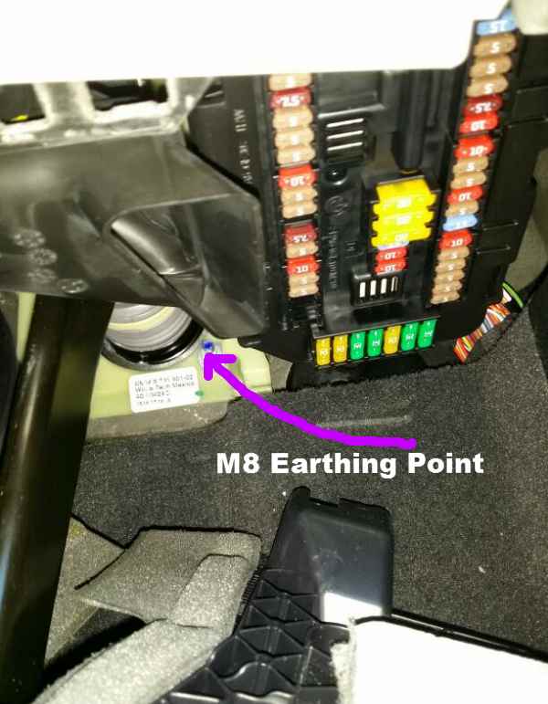
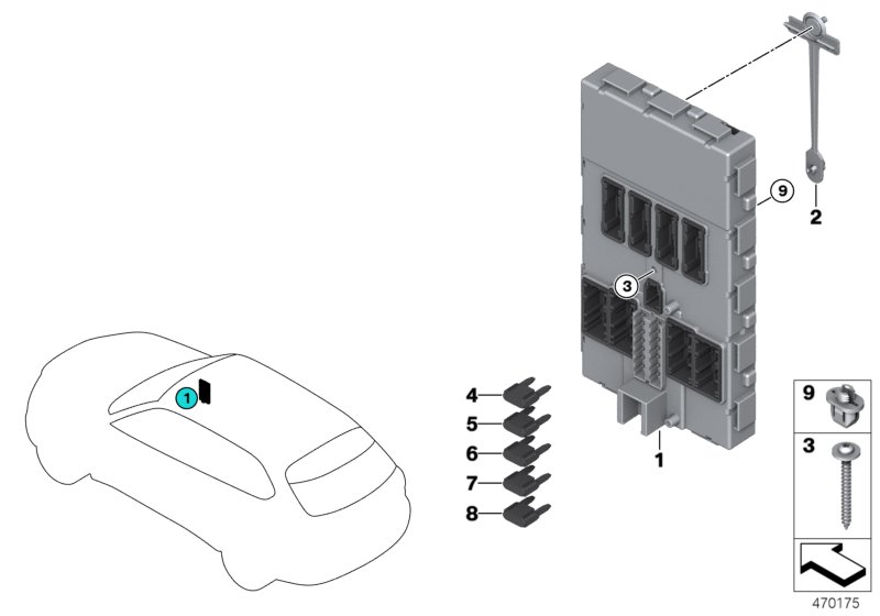
Electronic control unit
This element is attached to the A-pillar near the passenger’s feet and is covered by the interior trim.
In this video you can see how to get to this module using the example of a right-hand BMW X5 F15.
The fuse group is in the center.
Diagram

Designation
- 30A Front passenger window drive
- 30A Rear power window drive on the driver’s side
- 20A Front passenger door lock
- 30A Power window drive driver
- 30A Heated rear window
- 30A Rear power window drive from the passenger
- 20A Driver’s door lock
- –
- 5A Switching center in the steering column, light switch unit, driver assistance system control unit with hazard warning light switch
- 7.5A Left headlight
- 7.5A Diagnostic connector, heating and air conditioning system, dynamic stability control (DSC)
- 5A Telematic communication unit, electronic units of door handles
- 15A Horn (high/low tone)
- –
A little lower can be located the protection and control unit – Dynamic Stability Control (DSC)

Luggage compartment
Main fuse box
The main fuse box is located on the right side under the trunk lining.

Photo example

Diagram

Allocation
| 100 | 5A Parking brake button |
| 101 | 15A Right headlight |
| 102 | 5A High voltage battery pack |
| 103 | 5A Siren with tilt alarm |
| 104 | 5A Parking brake control unit, Natural Vacuum Leak Detection (NVLD) |
| 105 | 30A Electric reversible seat belt retractor right |
| 106 | 30A Torque distribution between rear axle wheels |
| 107 | 40A Automatic tailgate lift (→07.2016), tailgate function module (08.2016→) |
| 108 | – |
| 109 | – |
| 110 | 40A Air suspension compressor relay |
| 111 | – |
| 112 | 20A Hybrid pressure tank electronics |
| 113 | 30A Trailer electrical connection module |
| 114 | 30A Trailer electrical connection module |
| 115 | 20A Right headlight |
| 116 | 30A Parking brake control unit |
| 117 | 30A Electric reversible seat belt retractor left |
| 118 | 5A Video switcher (VSW) |
| 119 | – |
| 120 | 5A Power control unit |
| 5A N20: Charging box for additional battery | |
| 121 | 20A Head Unit |
| 122 | 30A Audio amplifier |
| 123 | – |
| 124 | 5A Video module |
| 125 | – |
| 126 | 10A Rear door closer drive (passenger side) |
| 127 | 5A DVD changer |
| 128 | 5A Wireless charging slot, antenna booster (wireless charging), base board |
| 129 | 15A Active Sound Design (ASD) |
| 130 | 5A Automatic tailgate lift |
| 131 | 5A Luggage compartment lighting, trunk button on rear lid from inside, noise filter |
| 132 | 5A Rear axle torque distribution, electronic ride height control |
| 133 | 5A Rear climate control |
| 134 | 10A Rear door closer drive (driver’s side) |
| 135 | 5A gas generator emergency shutdown terminals |
| 136 | – |
| 137 | – |
| 138 | – |
| 139 | 20A Trailer socket |
| 140 | 20A Trunk lid lock |
| 141 | – |
| 142 | – |
| 143 | 10A Refrigerator relay |
| 144 | 15A Control unit for selective catalytic reduction (SCR – Selective Catalytic Reduction) |
| 145 | 5A Parking aid, information system fan |
| 146 | 15A Silencer electric shutter (#1, #2) |
| 147 | 15A Control unit for selective catalytic reduction (SCR – Selective Catalytic Reduction) |
| 148 | 5A Lane change warning (SWW) |
| 149 | 7.5A Right headlight |
| 150 | 5A -06.2016: Contactless trunk release electronic return unit, electronic comfort charge (hybrid) |
| 7.5A 07.2016+: Contactless tailgate system return electronic unit, comfort electronic charge (hybrid), tailgate function module | |
| 151 | 5A USB-HUB (USB connector #1/#2, AUX-In connector) |
| 152 | 5A Electric reversible seat belt retractor left/right |
| 153 | 15A Control unit for selective catalytic reduction (SCR – Selective Catalytic Reduction) |
| 154 | 5A Surround View Camera (TRSVC), rear view camera |
| 155 | 10A Front passenger’s door closer drive |
| 156 | 10A Driver’s door closer drive |
| 157 | – |
| 158 | 10A Rear audio system |
| 159 | 5A Audio amplifier, information system fan |
| 160 | 20A Rear heater |
| 161 | – |
| 162 | 20A Second row sockets, luggage compartment socket |
| 163 | 30A Trailer electrical connection module |
| 164 | 30A Heated rear right seat |
| 165 | 20A Fuel pump control unit (EKPS) |
| 166 | 30A Heated rear left seat |
| 167 | 30A Driver’s door closer actuator, front passenger’s door closer actuator |
Check the information with your diagram on the paper brochure placed near the block.
Table with general designation of fuses

It’s not difficult to figure it out. For example, fuse 13 is responsible for the sound signal, for the phone – 25, 128, for heated rear window – 5, heated seats – 26, 65, 64, 164, 166 and so on.
The fuses 36, 37, 143, 162 are responsible for the cigarette lighter. See the diagrams for their location.
Relay elements are located next to the box. For example, air suspension and refrigerator relays (if equipped in a car).
Battery fuses
High power fuses are built into the battery cover to protect all circuits.

Diagram

Appointment
| 500 | 50A Central body control unit – Body Domain Controller (BDC) |
| 501 | 125A Fuse box in the luggage compartment |
| 502 | 150A Dynamic Stability Control (DSC) |
| 503 | 125A N63, S63, N20: Built-in power module |
| 125A D47, N47, N57: Main engine management relay (DDE) | |
| 504 | 125A Central control unit for body electronics – Body Domain Controller (BDC) |
| 505 | 50A Audio amplifier |
| 506 | 60A N55, N63, S53, B47, N47, N57: Power Control Unit (PCU) |
| 60A N20: Charging box for additional battery | |
| 507 | 40A Additional electric heater – rear right |
| 508 | 40A 3rd row auxiliary heating control unit |
| 509 | 40A Central body control unit – Body Domain Controller (BDC) |
| 510 | 40A Additional electric heater – rear left |
Additional fuse box
This block can be installed on the left side of the luggage compartment, it is also closed by the interior lining.

- 511 – 100A Additional fuses in the luggage compartment
- 512 – 100A Additional fuses in the luggage compartment
Diagram

Decoding
| 201 | 10A Additional control unit (SEC) power supply |
| 202 | 7.5A Additional control box |
| 203 | 5A Additional control unit (SEC) power supply |
| 204 | 5A Additional control unit (SEC) power supply |
| 205 | 5A Additional switching center |
| 206 | 5A Auxiliary audio module (simplex intercom, flashing beacons, pre-chamber speaker) |
| 207 | 20A Additional audio module |
| 208 | 5A Auxiliary audio module (simplex intercom, flashing beacons, pre-chamber speaker) |
| 209 | 5A Additional audio module |
| 210 | 5A Additional control unit (SEC) power supply |
| 211 | 20A Heated windshield |
| 212 | 20A Heated windshield |
| 213 | 15A Heated left/right front side window |
| 214 | 5A Additional control box |
| 215 | 5A Additional control box |
| 216 | 5A Additional control box |
| 217 | 5A Auxiliary audio module (simplex intercom, flashing beacons, pre-chamber speaker) |
| 218 | 5A Additional control box |
| 219 | 5A Additional audio module |
| 220 | 5A Additional control box |
Diagram

Assignment
| 301 | 10A Additional control box |
| 302 | 5A Additional switching center |
| 303 | 5A Auxiliary audio module (simplex intercom, flashing beacons, pre-chamber speaker) |
| 304 | 5A Additional control unit (SEC) power supply |
| 311 | 30A Power window |
| 312 | 30A Power window |
| 313 | 30A Power window |
| 314 | 30A Power window |
| 615 | 5A Electronic machine control (EME) |
| 612 |
Engine compartment
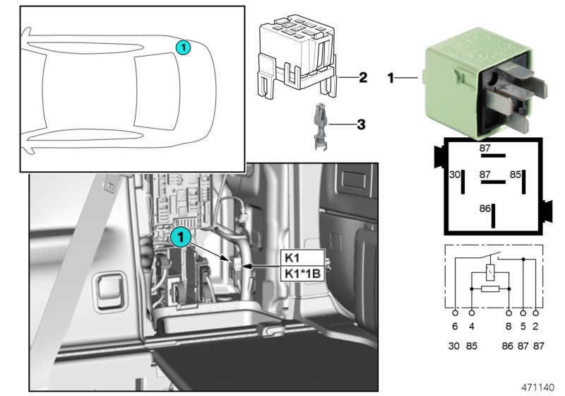
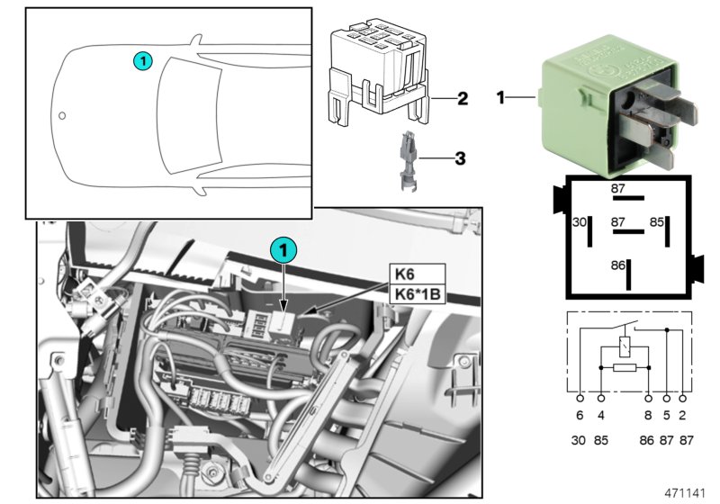
Fuse and relay box
On the right, in the assembly compartment, there is another box with fuses and relays.
DDE engine relay K6 and box diagram
Designation
| 1 | 20A Camshaft Position Sensor, Quantity Control Valve, Rail Pressure Control Valve, Turbine Control Gate Pressure Converter, Low Pressure Compressor Bypass Valve Changeover Valve (Except USA), EGR Auxiliary Cooler Bypass Changeover Valve (USA), Regulator boost pressure (power class “T”), boost pressure regulator – high pressure stage (variable turbocharger geometry (power class “S”)), boost pressure regulator No. 2 – high pressure stage (variable turbocharger geometry (N57D30S1)) |
| 2 | 20A Lambda probe upstream of catalytic converter, hot film air mass meter, engine mount stiffness control valve, lambda probe downstream of catalytic converter, oil condition sensor, EGR cooler bypass flap changeover valve, high pressure compressor sequence changeover valve #2, pressure transducer for overflow valve |
| 3 | 30A Diesel engine management system (DDE) |
| 4 | 10A Nitrogen oxide sensor before SCR catalytic converter, EGR coolant pump (→04.2014), EGR low temperature cooling changeover valve, diesel particle sensor |
| 5 | 10A Pressure converter for bypass valve, turbine control flap changeover valve, coolant pump relay |
Fuse box
Unattended fuse blocks can be installed separately.

Allocation
| 400 | 125A Electric fan open relay |
| 401 | 125A Electromechanical power steering (EPS) |
| 402 | 100A Additional electric heater |
| 403 | 50A Fuel filter heater |
and fuses and protection relays for the Engine Management System (DME) (fuel injection system).
Check out our YouTube video for more on this topic. Don’t forget to subscribe!
Anything to add? We will be glad to receive your comments.
I need to tap of 12VDC 30Amp for an equipment rack in the trunk of the vehicle, Where is the best place to tap this power and only when the vehicle is started on in ACC mode on ignition?
Any info on the power distribution module under the cabin filter in the hood? I know the fuses are non serviceable but would like to know their appointment including the relays