Toyota Camry Vista Sv40 represents the 4th generation of the model which was produced in 1994, 1995, 1996, 1997 and 1998. In this material, we will show a description of fuses and relays Toyota Vista sv40 with box diagrams and their locations. Note the cigarette lighter fuse.

Passenger compartment
Fuse box is located under the panel, behind a protective cover.

Diagram

Assignment
- GAUGE Instruments 10A
- WIPER Wipers and washers 25A
- CIG Cigarette lighter 15A
- IDLE UP Boost XX 5A
- STARTER Starter 7,5A
- IGN Ignition 5A
- FOG Fog lights 15A
- STOP Stop signals 15A
- AM1 Ignition switch 1 circuit 40A
- POWER Windows, hatches 30A
- DOOR Central locking 30A
- TAIL Dimensions 7.5A
- DEF Heated rear window 30A
- PANEL Instrument Cluster 5A
- RADIO №2 Radio 15A
- TURN Direction indicators 10A
- HTR Heater 10A
- ELECTONIC IG Ignition 15A
The fuse number 3, 15A, is responsible for the cigarette lighter.
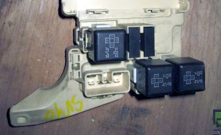
Some relays are attached to the back of the unit.
Photo – example
Diagram

Designation
- Integrated relay
- Tailgate relay
- Heated rear window relay
- RFI filter
- RFI filter
- Main power relay
Engine compartment
Fuse and relay box
Located on the left side of the engine compartment.

Diagram

Protected components
- CDS FAN Condenser fan (4S-FE, 3S-FE) 30A
- DOME Interior lighting 10A
- EFI Injection system 15A
- RADIO №1 Radio tape recorder 15A
- ECU-B Mirror Control, 5A Remote Lock
- HAZARD Alarm 10A
- HEAD RH Right headlight 10A
- HEAD LH Left headlight 10A
- TRC Traction control 7.5A
- DEICER De-icer 20A
- AM # 2 Ignition lock circuit # 2 20A
- 4WS No. 2 System 4WS 30A
- ALT-S 5A generator circuit
- 4WS No. 1 System 4WS 30A
- HORN Buzzer 10A
- MAIN Main fuse-link 40A
- HTR Heater 40A
- RAD FAN Radiator Fan 30A
- ABS – 60A
- ALT Generator 100A
- A HEAD LAMP Headlight Relay
- B EFI Fuel pump relay (4S-FE, 3S-FE)
- C STARTER Starter relay
- D HORN Signal relay
- E HEATER Heater relay
- F MAG.CLUTCH Compressor electromagnetic clutch relay
- G MAIN ENGINE Engine Main Relay (4S-FE, 3S-FE)
Relay boxes
Box 1 (Right side of the engine compartment)

Box 2 (Left side of the engine compartment)

Decoding
- Turn signal interrupter relay
- Anti-icer relay
- Fog lamp relay
- Turning light relay
- Diode of the relay of lighting lamps when turning
- Fuel pump relay
- Relay for idle speed increase when the heater is turned on
Box 3 (Left side of the engine compartment)

ABS Box (Rigth side of the engine compartment)

Assignment
- Radiator fan relay
- Radiator fan relay
- Radiator fan relay
- Relay for ABS solenoid valves
- ABS drive relay
There is something to add to the material – write in the comments.
May provide with wiring diagram to more under stand to solve problem
did you find the wiring diagram/color code for this car? I’m trying to install a keyless entry and i keep getting incorrect information