The 4th generation Toyota RAV4 is marked XA40 / CA40 and was produced in 2013, 2014, 2015, 2016, 2017, 2018 and 2019. During this time, the model has been updated. In this publication, we will provide information on the location of electronic control units, a detailed description of fuses and relays Toyota Rav 4 4 generations with box diagrams and photographs. Highlight the cigarette lighter fuse.

Check the designation of the elements with your diagrams on the protective cover of the unit.
Contents
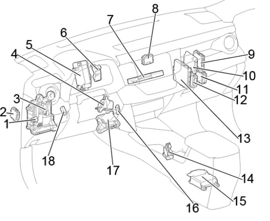
Passenger compartment
Location
Layout of electronic control units
LHD
RHD
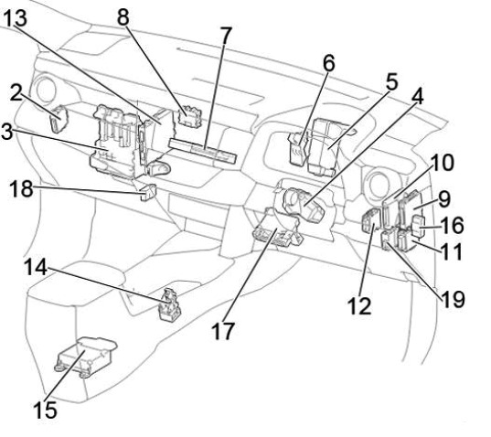
Assignment
- LHD: Interior lighting relay (DOME CUT)
- Headlight range control unit
- Fuse Box / Body ECM
- Steering lock actuator
- Power steering control unit
- Relay box
- Navigation control unit
- Four-wheel drive control unit
- Parktronic control unit (Clearance Warning)
- Driver assistance systems control unit
- Network gateway block
- Wiper relay
- Start-stop system control unit
- Gear selector control unit
- Airbag control unit
- Distribution connector
- Air conditioner amplifier
- Distribution connector
- RHD: Double Door Lock Relay
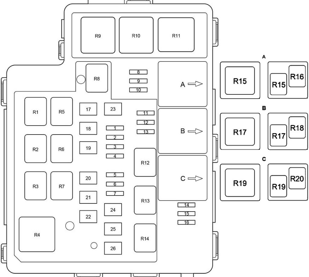
Fuse box
Located under the dashboard. In the diagram, this box is indicated under the number 3.

Photo
Circuits protected
| 1 | – |
| 2 | 7,5A STOP – Brake lights |
| 3 | 10A S / ROOF – Hatch |
| 4 | 5A AM1 – Fuses: “IG1 NO.1”, “IG1 NO.2”, “IG1 NO.3”, “ACC” |
| 5 | 7,5A OBD – Diagnostic connector |
| 6 | 20A D / L NO.2 – Before October 2015: Central locking, body ECU |
| 7 | 7,5A FOG RR – Rear fog light |
| 8 | 10A D / L BACK – Central locking (tailgate) |
| 9 | 15A P / OUTLET NO.1 – Socket (cigarette lighter) |
| 10 | 20A DOOR D – Window regulator from the driver’s side |
| 11 | 20A DOOR R / R – Rear right power window |
| 12 | 20A DOOR R / L – Rear left power window |
| 13 | 15A WIP RR – Rear wiper |
| 14 | 15A WSH – Front glass washer, rear glass washer |
| 15 | 7,5A GAUGE – Reversing lamps, auto-dimming interior mirror, Blind Spot Monitor |
| 16 | 25A WIP FR – Windscreen wiper |
| 17 | 5A SFT LOCK-ACC – Lock the gear selector |
| 18 | 15A P / OUTLET NO.2 – Socket |
| 19 | 7,5A ACC – Sockets, audio system, power mirrors, body control unit, clock, current sensor |
| 20 | 7,5A PANEL – VSC OFF switch, instrument cluster, BSM switch, all-wheel drive switch, brush rest zone heating switch, multiport fuel injection system / sequential multiport fuel injection system, parking assistance systems, seat heating switches, sockets, door drive switch trunk, air conditioning control unit, rear window heating switch, audio system, steering wheel buttons, cup holder lights |
| 21 | 10A TAIL – Side light, license plate light, fog light |
| 22 | 20A D / L NO.2 – From October 2015: Central locking, body ECU |
| 23 | 5A EPS-IG – Power steering |
| 24 | 10A ECU-IG NO.1 – All Wheel Drive (Dynamic Torque Control), Steering Position Sensor, Instrument Cluster, Transmission Selector |
| 25 | 5A ECU-IG NO.2 – Body ECU, Wireless Control System, Gear Selector Lock, Intelligent Entry and Start System, Sunroof, Audio System, Tailgate Actuator, Tire Pressure Monitoring System, Blind Spot Monitoring System (Blind Spot Monitor), Lane Keeping Assist (LDA) |
| 26 | 7,5A HTR-IG – Air conditioning, heated rear window |
| 27 | 10A S-HTR LH – Heated left seat |
| 28 | 10A S-HTR RH – Heated right seat |
| 29 | 7,5A IGN – Fuel pump, multiport fuel injection system / sequential multiport fuel injection system, brake lights, steering lock |
| 30 | 7.5A A / B – Airbags, front passenger classification system |
| 31 | 5A METER – Instrument Cluster |
| 32 | 7,5A ECU-IG NO.3 – Generator, ABS / VSC, heating of the zone of rest of the brushes, brake lights, fuses: “FAN NO.1”, “FAN NO.2”, “FAN NO.3″, ” HTR “,” PTC “,” DEF “,” DEICER “ |
The cgarette lighter fuse is number 9.
Additional fuses are attached to the other side of the unit.

Diagram

Designation
- 30A P / SEAT F / L – Power left seat
- 30A PBD – Electric tailgate
- 30A P / SEAT F / R – Power right seat
- 30A P / W-MAIN – Front glass lifters, glass lifters control unit
Relay box

Diagram
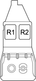
Functions
| R1 | LHD: Anti-theft system (S-HORN) RHD: Interior lighting (DOME CUT) |
| R2 | Rear fog light (FOG RR) |
Additional elements
Diagram

Assignment
- Sunroof control unit
- Receiver for central locking and tire pressure monitoring systems, Tire pressure monitoring system control unit
- Central locking receiver
- Phone transceiver
- Parking aid control unit
- Right sensor for blind spot monitoring
- Door control unit
- Blind Spot Monitor Left Sensor
- Fuel pump control unit
- Distribution connector
- Audio amplifier
Engine compartment
Location
General layout

Appointment
- Fuse and relay box
- The engine control unit
- Glow plug control unit
- Generator control unit
- From October 2015: Fan control unit
- Headlight wiper relay
- Transmission control unit
- Relay box
- Injector control unit
- Stepless valve lift controller
- Brake actuator
- Glow plug relay
- From Oct 2015: Fuel Heater Relay
Fuse and relay box

In the diagram is designated under the number 1 and is located on the left side of the engine compartment.
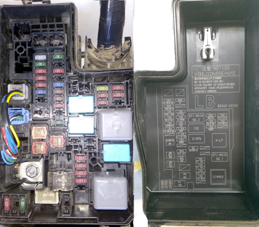
Type A
Diagram
Protected components
| 1 | 20A EFI-MAIN NO.1 – 2AR-FE: Multiport fuel injection system / sequential multiport fuel injection system, fuses: “EFI NO.1”, “EFI NO.2” |
| 25A EFI-MAIN NO.1 – 3ZR-FE, 3ZR-FAE: Multiport fuel injection system / sequential multiport fuel injection system, fuses: “EFI NO.1”, “EFI NO.2” | |
| 30A EFI-MAIN NO.1 – Diesel: Multiport fuel injection system / sequential multiport fuel injection system, gearbox control unit, fuse: “EFI NO.3” | |
| 2 | 30A TOWING-B – Trailer connector |
| 3 | 10A STRG LOCK – Steering lock |
| 4 | 10A ECU-B NO.2 – Air Conditioning, Instrument Cluster, Intelligent Entry and Start System, Roof Module |
| 5 | 10A TURN & HAZ – Instrument Cluster |
| 6 | 20A EFI-MAIN NO.2 – 2AR-FE: Air flow sensor, fuel pump, rear oxygen sensor |
| Diesel: fuses: “EFI NO.1”, “EFI NO.2” | |
| 15A EFI-MAIN NO.2 – 3ZR-FE, 3ZR-FAE: Multiport fuel injection system / sequential multiport fuel injection system | |
| 7.5A EFI-MAIN NO.2 – From October 2015: 2WW: Multiport fuel injection system / sequential multiport fuel injection system | |
| 7 | 20A ST NO.2 – Before October 2015: Starting system |
| 30A D / L NO.1 – From October 2015: Trunk door, instrument cluster, dual lock, smart entry and start system, fog lights, wiper and washer, headlights, immobilizer, interior lighting, power windows, rear fog light, seat belt indicator , airbags, starting system, steering lock, anti-theft system, tire pressure monitoring system, wireless control system | |
| 8 | 30A ST – Starting system |
| 30A ST NO.1 – Starting system | |
| 9 | 30A AMP – Audio system |
| 30A AMP / BBC NO.3 – From October 2015: Audio System | |
| 10 | 10A ETCS – Multiport fuel injection system / sequential multiport fuel injection system |
| 30A FUEL PMP – From October 2015: 2WW: Fuel Pump | |
| 11 | 10A S-HORN – Before October 2015: Anti-theft system |
| 30A BBC NO.2 – From October 2015 (without telematics system): Start-stop system | |
| 7,5A MAYDAY – From October 2015: Telematics system | |
| 12 | 15A IG2 – Multiport fuel injection system / sequential multiport fuel injection system, fuses: “METER”, “IGN”, “A / B” |
| 13 | 7,5A AM2 – Starting system, fuse: “IG2” |
| 14 | 7,5A ALT-S / ICS – Current sensor, generator |
| 15 | 10A HORN – Sound signal |
| 16 | 25A EDU – Diesel: Multiport fuel injection system / sequential multiport fuel injection system |
| 20A ST NO.2 – From October 2015: 3ZR-FAE: Starting system | |
| 10A S-HORN – From October 2015: Anti-theft system | |
| 17 | 30A D / C CUT – Fuses: “DOME”, “ECU-B NO.1”, “RADIO” |
| 18 | 5A WIPER-S – Wiper switch, current sensor, multiport fuel injection system / sequential multiport fuel injection system |
| 19 | 10A EFI NO.1 – 3ZR-FE: Air flow sensor, VSV, ACIS VSV, rear oxygen sensor, multiport fuel injection system / sequential multiport fuel injection system |
| 10A EFI NO.1 – 3ZR-FAE: Multiport fuel injection system / sequential multiport fuel injection system | |
| 10A EFI NO.1 – 2AR-FE: Air flow sensor, VSV, ACIS VSV | |
| 10A EFI NO.1 – 1AD-FTV: Air flow sensor, oil valve, EDU, ADD FUEL VLV, EGR, start-stop system, glow plugs | |
| 10A EFI NO.1 – 2AD-FTV, 2AD-FHV: EDU, ADD FUEL VLV, EGR, air flow sensor, VNT E-VRV | |
| 7.5A EFI NO.1 – From October 2015: 2WW: Multiport fuel injection system / sequential multiport fuel injection system | |
| 20 | 10A EFI NO.2 – 3ZR-FAE: Air flow sensor, VSV, ACIS VSV, rear oxygen sensor, start-stop system |
| 10A EFI NO.2 – 2AR-FE: Multiport fuel injection system / sequential multiport fuel injection system | |
| 10A EFI NO.2 – 3ZR-FE, 2AD-FTV, 2AD-FHV: Air flow sensor | |
| 15A EFI NO.2 – From October 2015: 2WW: Multiport fuel injection system / sequential multiport fuel injection system | |
| 21 | 10A H-LP LH-HI – High beam left, high beam indicator |
| 22 | 10A H-LP RH-HI – High beam right |
| 23 | 7.5A EFI NO.3 – Multiport fuel injection system / sequential multiport fuel injection system, transmission control unit |
| 20A EFI NO.3 – From October 2015: 2WW: Multiport fuel injection system / sequential multiport fuel injection system | |
| 24 | – |
| 25 | – |
| 26 | 20A RADIO – Radio and audio system |
| 27 | 10A ECU-B NO.1 – Body electrical control unit, wireless control system, steering wheel position sensor, central locking, clock, electric tailgate, tire pressure monitoring system |
| 28 | 10A DOME – Interior lighting, luggage compartment lighting, personal lighting |
| 29 | 10A H-LP LH-LO – Before October 2015: Halogen bulbs: Low beam, headlight range control From October 2015: Low beam left, headlight range control |
| 15A H-LP LH-LO – Before October 2015: HID: Low beam left, headlight range control | |
| 30 | 10A H-LP RH-LO – Before October 2015: Halogen bulbs: Low beam right From October 2015: Low beam right |
| 15A H-LP RH-LO – Before October 2015: HID: Low Beam Right | |
| 31 | – |
| 32 | – |
| 33 | – |
| 34 | – |
| 35 | 50A FUEL HTR – From October 2015: 2WW: Fuel heating |
| 36 | 40A BBC – Start-stop system |
| 37 | 30A VLVMATIC – VALVEMATIC system |
| 50A EFI MAIN – From October 2015: 2WW: ABS, Cruise Control, Hill Descent Assist, Hill Start Assist, Start / Stop System, Panoramic Vision System, Dynamic Cruise Control Radar, TRC, VSC | |
| 38 | 30A ABS NO.2 – VSC, ABS |
| 39 | 50A ABS NO.2 – VSC, ABS |
| 40 | 50A H-LP-MAIN – Fuses: “H-LP RH-LO”, “H-LP LH-LO”, “H-LP RH-HI”, “H-LP LH-HI” |
| 41 | 80A GLOW – Glow plugs |
| 42 | 80A EPS – Electric power steering |
| 43 | 120A ALT – Before October 2015: Petrol: Fuses: “STOP”, “S / ROOF”, “AM1”, “OBD”, “D / L NO.2”, “FOG RR”, “D / L BACK”, “P / OUTLET NO.1”, “DOOR D”, “DOOR R / R”, “DOOR R / L”, “WIP RR”, “WSH”, “GAUGE”, “WIP FR”, “SFT LOCK- ACC “,” P / OUTLET NO.2 “,” ACC “,” PANEL “,” TAIL “,” D / L NO.2 “,” EPS-IG “,” ECU-IG NO.1 “,” ECU -IG NO.2 “,” HTR-IG “,” S-HTR LH “,” S-HTR RH “,” IGN “,” A / B “,” METER “,” ECU-IG NO.3 “ |
| 140A ALT – Before October 2015: Diesel, (3ZR-FAE from April 2015): From October 2015: Except 2WW: Fuses: “ABS NO.1”, “ABS NO.2”, “RDI FAN”, “FAN NO. 1 “,” S / HTR R / L “,” DEICER “,” FOG FR “,” S / HTR R / R “,” CDS FAN “,” FAN NO.2 “,” HTR “,” STV HTR ” , “TOWING-ALT”, “HWD NO.1”, “HWD NO.2”, “H-LP CLN”, “DRL”, “PTC HTR NO.1”, “PTC HTR NO.2”, “PTC HTR NO.3 “,” DEF “,” NOISE FILTER “,” STOP “,” S / ROOF “,” AM1 “,” OBD “,” D / L NO.2 “,” FOG RR “,” D / L BACK “,” P / OUTLET NO.1 “,” DOOR D “,” DOOR R / R “,” DOOR R / L “,” WIP RR “,” WSH “,” GAUGE “,” WIP FR “, “SFT LOCK-ACC”, “P / OUTLET NO.2”, “ACC”, “PANEL”, “TAIL”, “D / L NO.2”, “EPS-IG”, “ECU-IG NO.1 “,” ECU-IG NO.2 “,” HTR-IG “,” S-HTR LH “,” S-HTR RH “,” IGN “,” A / B “,” METER “,” ECU-IG NO .3 “ | |
| Relay | |
| R1 | Engine control unit (EFI-MAIN NO.2) |
| R2 | Ignition (IG2) |
| R3 | Diesel: Engine Control Unit (EDU), Petrol: Fuel Pump (C / OPN), 2WW: Fuel Pump (FUEL PMP) |
| R4 | Before October 2015: Lights (H-LP), From October 2015: Dimmer |
| R5 | Engine control unit (EFI-MAIN NO.1) |
| R6 | Before Oct 2015: Dimmer |
| From October 2015: Except 2AR-FE: Headlights (H-LP), 2AR-FE: Headlights / Daytime Running Lights (H-LP / DRL) | |
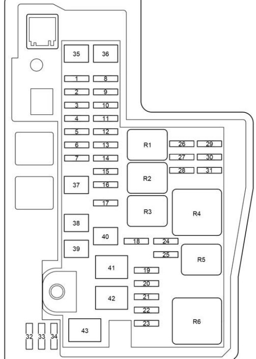
Type B
Diagram
Decoding
| 1 | 20A RADIO – Audio system |
| 2 | 10A ECU-B NO.1 – Body ECM, Wireless Control System, Steering Position Sensor, Clock, Power Tailgate, Tire Pressure Monitoring System, Driver Position Memory |
| 3 | 10A DOME – Interior lighting, personal lighting, luggage compartment lighting, individual mirror lighting |
| 4 | – |
| 5 | 20A DEICER – Heated brush rest zone |
| 6 | – |
| 7 | 7,5A FOG FR – Fog light, fog light indicator |
| 8 | 30A AMP – Audio system |
| 9 | 30A ST – Starting system |
| 10 | 20A EFI-MAIN NO.1 – Multiport fuel injection system / sequential multiport fuel injection system, fuses: “EFI NO.1”, “EFI NO.2” |
| 11 | – |
| 12 | 15A IG2 – Multiport fuel injection system / sequential multiport fuel injection system, fuses: “METER”, “IGN”, “A / B” |
| 13 | 10A TURN & HAZ – Instrument Cluster |
| 14 | 7,5A AM2 – Starting system, fuse: “IG2” |
| 15 | 10A ECU-B NO.2 – Air Conditioning, Instrument Cluster, Front Passenger Classification System, Intelligent Entry and Start System |
| 16 | 10A STRG LOCK – Steering lock |
| 17 | 30A D / C CUT – Fuses: “DOME”, “ECU-B NO.1”, “RADIO” |
| 18 | 10A HORN – Sound signal |
| 19 | 10A ETCS – Multiport fuel injection system / sequential multiport fuel injection system |
| 20 | 20A EFI-MAIN NO.2 – Air flow sensor, fuel pump, rear oxygen sensor |
| 21 | 7,5A ALT-S / ICS – Current sensor |
| 22 | 10A MIR HTR – Heated mirrors, multiport fuel injection system / sequential multiport fuel injection system |
| 23 | 10A EFI NO.1 – Air flow sensor, VSV, ACIS VSV |
| 24 | 10A EFI NO.2 – Multiport fuel injection system / sequential multiport fuel injection system |
| 25 | 10A H-LP LH-HI – High beam left, high beam indicator |
| 26 | 10A H-LP RH-HI – High beam right |
| 27 | – |
| 28 | 10A H-LP LH-LO – Low beam left |
| 29 | 10A H-LP RH-LO – Low beam right |
| 30 | 30A CDS FAN – Cooling fan |
| 31 | 50A HTR – Air Conditioner |
| 32 | 50A H-LP-MAIN – Daytime running lights, fuses: “H-LP RH-LO”, “H-LP LH-LO”, “H-LP RH-HI”, “H-LP LH-HI” |
| 33 | 30A PTC HTR NO.2 – Auxiliary heater |
| 34 | PTC HTR NO.1 – Auxiliary heater |
| 35 | 30A DEF – Heated rear window, fuse: “MIR HTR” |
| 36 | 30A ABS NO.2 – VSC |
| 37 | 30A RDI FAN – Cooling fan |
| 38 | 50A ABS NO.1 – VSC |
| 39 | 80A EPS – Electric power steering |
| 40 | 120A ALT – Fuses: “ABS NO.1”, “ABS NO.2”, “PTC HTR NO.1”, “PTC HTR NO.2”, “DEICER”, “HTR”, “RDI FAN”, “CDS FAN “,” FOG FR “,” DEF “ |
| 41 | 5A WIPER-S – Wiper switch, rain sensor |
| 42 | 10A SPARE – Spare fuse |
| 43 | 20A SPARE – Spare fuse |
| 44 | 30A SPARE – Spare fuse |
| M1 | Daytime running lights module |
| Relay | |
| R1 | Engine control unit (EFI-MAIN NO.2) |
| R2 | Ignition (IG2) |
| R3 | Fuel pump (C / OPN) |
| R4 | Jumper |
| R5 | Headlights (H-LP) |
| R6 | Engine control unit (EFI-MAIN NO.1) |
| R7 | Heated rear window (DEF) |
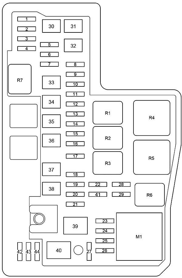
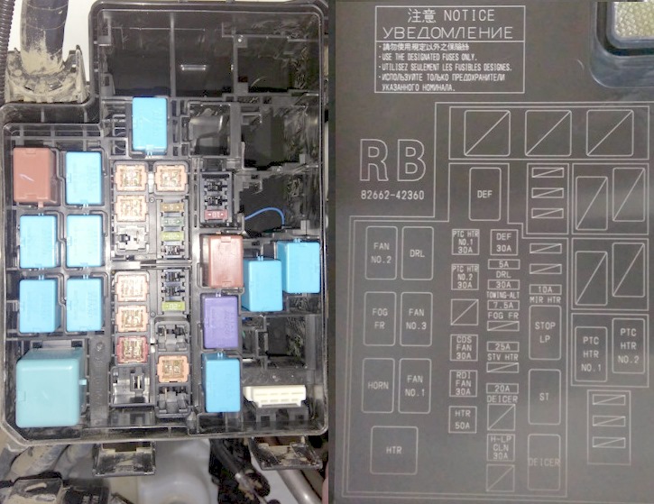
Relay box
In the diagram it is designated under the number 8. Located on the right side of the engine compartment.

Photo – an example of execution
Type A
Diagram
Assignment
| 1 | 5A DRL – Daytime running lights |
| 2 | 30A TOWING-ALT – Trailer connector |
| 3 | 7,5A FOG FR – Fog light, fog light indicator |
| 4 | 10A NOISE FILTER – Noise filter |
| 5 | 25A STV HTR – Auxiliary heater |
| 6 | 10A S / HTR R / R – From October 2015: Heated rear seat |
| 7 | 20A DEICER – Heated brush rest zone |
| 10A S / HTR R / L – From October 2015: Heated rear seat | |
| 8 | CDS FAN NO.2 – From October 2015: Diesel: Cooling Fan |
| 9 | – |
| 10 | 5A RDI FAN NO.2 – From October 2015: Diesel: Cooling Fan |
| 11 | – |
| 12 | – |
| 13 | 10A MIR HTR – Heated mirrors, multiport fuel injection system / sequential multiport fuel injection system |
| 14 | – |
| 15 | – |
| 16 | – |
| 17 | 50A PTC HTR NO.1 – 600W, 840W: Auxiliary heater |
| 30A PTC HTR NO.1 – 330W: Auxiliary heater | |
| 18 | 50A PTC HTR NO.2 – 840W: Auxiliary heater |
| 30A PTC HTR NO.2 – 330W: Auxiliary heater | |
| 19 | 50A PTC HTR NO.2 – 840W: Auxiliary heater |
| 30A PTC HTR NO.2 – 330W: Auxiliary heater | |
| 20 | 30A CDS FAN – Cooling fan |
| 40A CDS FAN – From October 2015: 2WW: Cooling Fan | |
| 50A FAN NO.2 – From October 2015: Trailer + Diesel: Cooling Fan | |
| 21 | 30A RDI FAN – Cooling fan |
| 40A RDI FAN – From October 2015: 2WW: Cooling Fan | |
| 50A FAN NO.1 – From October 2015: Trailer + Diesel: Cooling Fan | |
| 22 | 50A HTR – Air Conditioner |
| 23 | 30A DEF – Heated rear window, fuse: “MIR HTR” |
| 24 | 50A HWD NO.2 – Heated windshield |
| 25 | 30A H-LP CLN – Headlight cleaners |
| 26 | 50A HWD NO.1 – Heated windshield |
| Relay | |
| R1 | Cooling fan (FAN NO.2) |
| R2 | Front fog light (FOG FR) |
| R3 | Sound signal |
| R4 | Heater (HTR) |
| R5 | Daytime running lights (DRL) |
| R6 | Cooling fan (FAN NO.3) |
| R7 | Cooling fan (FAN NO.1) |
| R8 | Heated rear window (DEF) |
| R9 | Auxiliary heater (PTC HTR NO.1) |
| R10 | Auxiliary heater (PTC HTR NO.2) |
| Heated windshield (HWD NO.1) | |
| R11 | Auxiliary heater (PTC HTR NO.3) |
| Heated windshield (HWD NO.2) | |
| R12 | Stop lamps (STOP LP) |
| R13 | Starter (ST), (ST NO.1) |
| R14 | Heated brush rest zone (DEICER) |
| Heated steering wheel (STRG HTR) | |
| Heated brush rest zone / heated steering wheel (DEICER / STRG HTR) | |
| A | |
| R15 | From October 2015: Trailer + Diesel: Cooling fan (FAN NO.1), Heated rear seat (S / HTR R / L) |
| R16 | From October 2015: Heated rear seat (S / HTR R / R) |
| B | |
| R17 | From October 2015: Trailer + Diesel: Cooling fan (FAN NO.2), Heated glass washer nozzles (WSH NZL HTR) |
| R18 | Starter (ST NO.2) |
| C | |
| R19 | 330W: Auxiliary heater (PTC HTR NO.1) |
| 600W: Auxiliary heater (PTC HTR NO.3) | |
| R20 | Auxiliary heater (PTC HTR NO.2) |
Type B
Diagram
Designation
| R1 | Front fog lights (FOG FR) |
| R2 | A / C Compressor Clutch (MG / CLT) |
| R3 | PTC heater (PTC HTR # 2) |
| R4 | – |
| R5 | Horn |
| R6 | Electro cooling fan (FAN # 2). |
| R7 | PTC heater (PTC HTR # 1) |
| R8 | Electro cooling fan (FAN # 3). |
| R9 | Starter (ST) |
| R10 | Electro cooling fan (FAN # 1) |
We have posted a video on our YouTube channel. Watch and subscribe.
If you have any questions or have something to add – write in the comments.
I’m looking for the location of the relay for the electric windows on a 2016 rav4 xle
where is the fuse for cruise control located on 2014 Rav4 XLE?
Bonjour, j’ai un RAV4 2016 AX40 4ème Gén. et qui a l’alarme anti vol qui ne fonctionne pas (physiquement), l’indicateur lumineux est opérationnel mais l’alarme sonore ne se déclenche pas quand on secoue la voiture, je l’ai acheté ainsi d’occasion, veuillez s’il vous plaît m’indiquer la procédure à suivre ou ce que vous voulez pour la faire fonctionner.
Merci d’avance.