Toyota Starlet was produced in 5 generations. In this article you will find information on the location of electronic control units, a description of fuses and relays Toyota Starlet with box diagrams for cars produced in 1989, 1990, 1991, 1992, 1993, 1994, 1995, 1996, 1997, 1998, 1999 representing 4 and 5th generation designated P80 and P90, respectively. Highlight the cigarette lighter fuse.
The design of the boxes and their location depends on the year of manufacture and the level of equipment of your car.
Contents
P80
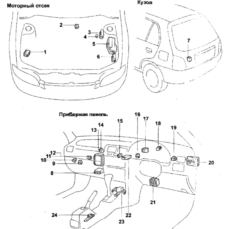
Location
Diagram

Assignment
- mounting block # 1 (J / B # 1)
- power relay box (main relay and thermal fuse)
- combination switch
- local illumination lamp
- interior lamp
- limit switch
- mounting block # 2 (J / B # 2)
- start inhibit switch (automatic transmission)
- reversing light switch (manual transmission)
- ALT 100А (1N) or ALT 80А (cars with gasoline engines and automatic transmission)
- AM1 50A (cars with a diesel engine and with gasoline engines and automatic transmission)
- horn relay
- relay for additional heating element (1N, versions)
- main motor relay
- AM1 60A (cars with gasoline engines and manual transmission)
- headlight
- anti-fog headlight
- front turn signal
- rear combination lamp
- additional brake light
- license plate light
- lighting warning relay
- fog lamp switch
- turn signal interrupter relay
- brake light switch
- alarm switch
Passenger compartment fuse box
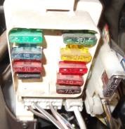
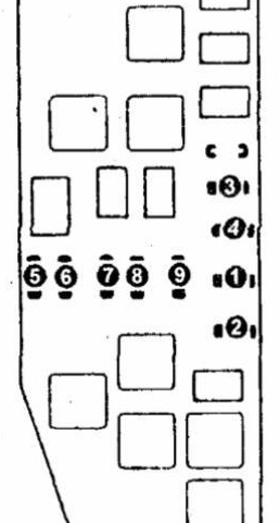
Diagram
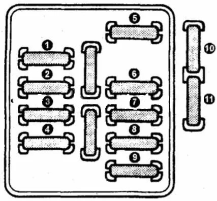
Protected components
| 1 | 10A RADIO CIG (radio, cigarette lighter, electric mirrors, clock) |
| 2 | 15A TAIL (clock and radio illumination) |
| 3 | 10A STOP (brake lights) |
| 4 | 15A AM2 (AM2 circuit of the ignition switch – starting system) |
| 5 | 30A DEFOG (rear door glass heater) |
| 6 | 20A WIPER (front and rear wipers) |
| 7 | 7,5A TURN (direction indicators) |
| 8 | 10A A-C (air conditioner) |
| 9 | 7,5A GAUGE (instrument cluster, reversing light, tachometer, selector lock system) |
| 10 | 7,5A DEFOG IDLE-UP (engine management system and automatic transmission) |
| 20A FUEL HTR (electronic control unit for emission control system) | |
| 11 | 15A ECU-IG (TEMS, 4-channel ABS) |
The fuse number 1, 10A, is responsible for the cigarette lighter.
Engine compartment fuse and relay box
Type 1
Scheme
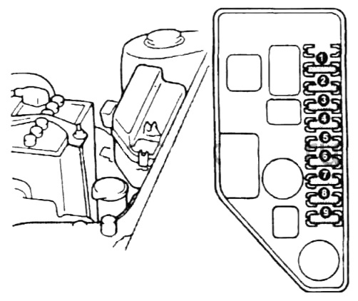
Designation
| 1 | 20A CONDENCER FAN (condenser fan) |
| 2 | 20A RADIATOR FAN (electric fan) (with ABS 30A) |
| 3 | 30A HITER (heater) |
| 4 | 10A HEAD (LH) (left headlight) |
| 5 | 10A HEAD (RH) (right headlight) |
| 6 | 15A DOME (interior lighting, clock, radio) |
| 7 | 15A AM2 (AM2 circuit of the ignition switch – starting system) |
| 8 | 15A HAZARD, HORN (horn and alarm) |
| 15A EFI (electronic engine control unit) | |
| 9 | 15A CUB (electronic carburetor control unit) |
| 30A SUB HEATOR (additional heater) |
Type 2
Diagram
Appointment
| 1 | 10A HEAD (LH) (left headlight) |
| 2 | 10A HEAD (RH) (right headlight) |
| 3 | 30A RTS (additional heater) |
| 4 | 10A AIRCON (air conditioner) |
| 5 | 15A EFI (electronic engine control unit) |
| 6 | 15A HAZARD (direction indicators and hazard warning lights) |
| 7 | 15A AM2 (AM2 circuit of the ignition switch – starting system) |
| 8 | 10A DOME (interior lighting) |
| 9 | 5A ALT-S (charging system) |
P90
Location
Decoding
- ABS relay
- glow plug relay (1N)
- relay box No. 3
- intake air heating relay (1N)
- engine compartment relay box
- relay box No. 6
- rear door glass wiper relay
- air conditioner amplifier
- size relay (up to 97.12)
- fuel pump relay (from 97.12)
- fuel pump relay (up to 97.12)
- size relay (from 97.12)
- electronic engine control unit
- selector lever lock system relay (from 97.12)
- warm-up control relay
- fog lamp relay (from 97.12) or selector lever lock system relay (up to 97.12)
- door lock control relay
- turn signal interrupter relay
- power relay unit
- electronic engine control unit
- fuse box
- air conditioning amplifier (automatic air conditioner)
- center airbag sensor
- deceleration sensor
Passenger compartment fuse box
Diagram
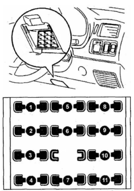
Protected components
| 1 | 30A DEFOG (rear door glass heater) |
| 2 | 7.5A MERT (instrument lighting, reversing lights) |
| 3 | 7,5A TURN (direction indicators) |
| 4 | 15A RADIO & LIGHTER (radio, cigarette lighter, electric mirrors, airbags) |
| 5 | 20A WIPER (wipers) |
| 6 | 5A ECU-IG (ABS) |
| 7 | 5A DEFOG IDLE-UP (engine management system and automatic transmission) |
| 8 | 15A TAIL (fog lights, dimensions, license plate lights, reverse, rear light) |
| 9 | 10A STOP (brake lights) |
| 10 | 5A ECU-B (airbags) |
| 11 | 5A IG (airbags) |
The fuse number 4, 15A, is responsible for the operation of the cigarette lighter.
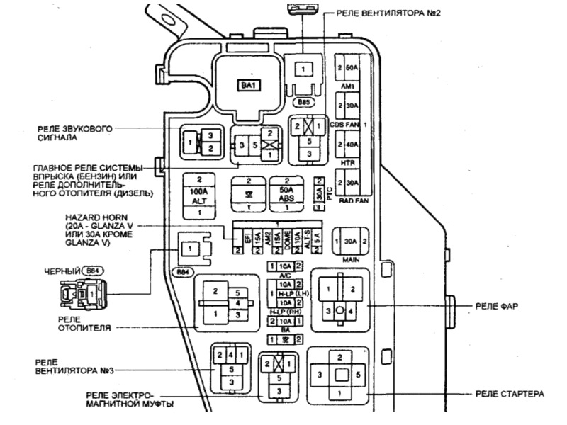
Engine compartment fuse and relay box
Type 1
Diagram

Relay
- R1 here horn relay
- R2 heater relay
- R3 main relay
- R4 fan relay
- R5 starter relay
Type 2
Diagram
I need to know parking light module for sterlet 1997
Hi, I was wondering if ep81 Toyota starlets have a starter motor relay
Thanks, found help.
My wipers do not switch off. Where is the problem? Starlet 1994 turbo