Toyota Corolla Verso AR10 was produced in 2004, 2005, 2006, 2007, 2008 and 2009. It was delivered all over the world, so you can find both right-hand drive and left-hand drive models. In this publication you can find information describing the location of the electronic control units, the purpose of all fuses and relays of the Toyota Corolla Verso with box diagrams and photo examples of their execution. Highlight the cigarette lighter fuse.

The arrangement of the boxes and the purpose of the elements in them may differ from the one presented and depend on the year of manufacture, the level of equipment and the region of delivery.
Contents
Engine compartment
Location
General layout of boxes in the cabin
LHD

RHD

Assignment
- Additional Fuse Box
- Body ECU
- Rear Window Defogger Relay
- Circuit Opening Relay
- Fuse Box
- Turn Signal Flasher
- Door Control Receiver
- Center Junction Block
- Transponder Key ECU
- A/C Control Assembly (Automatic A/C)
- A/C Amplifier
- Engine ECU
- Relay Box No.2
- Relay Box No.3
- Multi-mode Manual Transmission ECU
- Relay Box No.1
- Windshield Wiper Relay
- Clearance Sonar ECU
- Airbag Sensor Assembly Center
- Television Camera Controller
- Ignition Control ECU
Fuse box
It is located at the bottom of the dashboard behind a protective cover.
Photo – example

Diagram
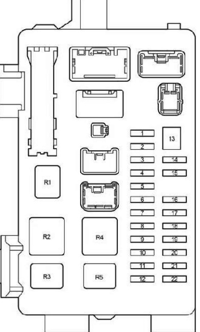
Protected components
| 1 | 10A IGN – SRS airbags, instrument cluster, starting system, multiport fuel injection system / sequential multiport fuel injection system |
| 2 | 20A S / ROOF – Hatch |
| 3 | 7,5A RR FOG – Rear fog light |
| 4 | 15A FR FOG – Front fog light, fog light indicator |
| 5 | 25A AM1 – Starting system, fuses: “CIG”, “RAD NO.1” |
| 6 | 7,5A PANEL – Instrument panel illumination, instrument cluster illumination, automatic transmission control unit, glove compartment illumination, armrest compartment illumination, headlight wipers, front fog light, parking aid, multi – information display |
| 7 | 20A RR WIP – Rear wiper and washer |
| 8 | 7,5A GAUGE2 – Reversing lamps, headlight range control, direction indicators, hazard warning lights |
| 9 | 15A CIG – Cigarette lighter |
| 10 | 10A HTR – Heated seats, air conditioning |
| 11 | – |
| 12 | 7,5A RAD NO.1 – Audio system, multi-information display, power mirrors, instrument cluster, socket |
| 13 | 30A PWR SEAT – Power Seats |
| 14 | 10A TAIL – Side light, license plate light, luggage compartment light, automatic light system, front fog light, rear fog light, instrument cluster |
| 15 | 7,5A OBD2 – Diagnostic connector |
| 16 | 15A P / POINT – Socket |
| 17 | 25A DOOR – Central locking |
| 18 | 25A WIP – Front wiper and washer, headlight wipers |
| 19 | 7,5A ECU-IG – Cooling Fan, Charging System, Power Steering, ABS, VSC |
| 20 | 20A S-HTR – Heated seats |
| 21 | 10A GAUGE1 – Light switch, multi – information display, integrated relay, instrument cluster, gear selector lock, automatic transmission control unit, rearview mirror, wiper, parking brake |
| 22 | 15A STOP – Stop lamps, gear selector lock, auxiliary brake light, multiport fuel injection system / sequential multiport fuel injection system |
| Relay | |
| R1 | Reserve |
| R2 | HTR – Heater |
| R3 | SEAT HTR – Heated seats |
| R4 | IG1 – Ignition |
| R5 | TAIL – Side light |
The fuse number 9 at 15A is responsible for the operation of the cigarette lighter.
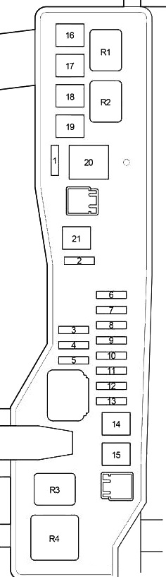
Additional fuse box
Diagram

Circuits protected
| 1 | 25A ACC – Push Button Start System, Engine Immobilizer System, Steering Lock System (LHD) |
| 2 | 20A P-RR P / W – Window regulator |
| 3 | 20A P-FR P / W – Window regulator |
| 4 | 20A D-RR P / W – Window Regulator |
| 5 | 20A D-FR P / W – Window regulator |
| 6 | 7,5A ECU-B 1 – Gearbox |
| 7 | 10A FUEL OPN – Fuel filler flap |
| 8 | 20A FR DIC – Heated area of windscreen wiper blades, fuse: “MIR HTR” |
| 9 | 10A A/C – Air Conditioner (Manual A/C), Power Heater (Hot Gas Type) |
| 10 | 7,5A DEF I / UP – Air conditioner |
| 11 | 7,5A ST – Multi – information display, multiport fuel injection system / sequential multiport fuel injection system, starting system |
| 12 | 10A MIR HTR – Heated mirrors |
| 13 | 15A RAD NO.2 – Audio system, multi – information display |
| 14 | 7,5A DOME – Interior lighting, personal lighting, door lighting, luggage compartment lighting, individual mirror lighting, footwell lighting |
| 15 | 7,5A ECU-B 2 – Air conditioning, wireless control system |
| 16 | 30A PWR SEAT – Power Seats |
Relay boxes
Diagram

Decoding
| Relay Box №1: | |
| R1 | Accessory (ACC) |
| R2 | Starter (ST) |
| Relay Box №2: | |
| R1 | Power Outlet |
| R2 | Ignition (IG2) |
| Relay Box №3: | |
| R1 | Front Fog Light |
| R2 | Rear Fog Light |
Additional elements

- Sliding Roof Control ECU
- Rear Wiper Motor Assembly
Engine compartment
Location
General arrangement of boxes under the hood

Appointment
- Fuse and relay Box
- Relay Box
- Headlight Cleaner Control Relay
- Skid Control ECU with Actuator
- Injector Driver (EDU)
- Glow Plug Relay
- Additional Fuse Box (1ZZ-FE, 3ZZ-FE)
- Additional Fuse Box (1CD-FTV)
Fuse and relay box
Located on the left side of the engine compartment.

Diagram
Type A

Type B
Assignment
| 1 | – |
| 2 | 25А VSC – 1CD-FTV: ABS, VSC |
| 25A ABS – 1CD – FTV: ABS | |
| 3 | – |
| 4 | – |
| 5 | – |
| 6 | 7,5A ALT-S – Charging system |
| 7 | 30A DCC – Fuses: “ECU-B NO.2”, “DOME”, “RAD NO.2” |
| 8 | 30A AM2 – Starting system, fuses: “ST”, “IGN” |
| 9 | 10A HAZARD – Direction indicators, hazard warning lights |
| 10 | 25A F-HTR – 1CD-FTV: Fuel heating |
| 11 | 15A HORN – Sound signal |
| 12 | 20A EFI – Multiport fuel injection system / sequential multiport fuel injection system, fuses: “EFI NO.1”, “EFI NO.2” |
| 13 | 25A PWR HTR – 1CD – FTV: Auxiliary heater |
| 14 | 30A RR DEF – Heated rear window |
| 15 | 40A MAIN – Headlight cleaners, headlights, fuses: “H-LP HI LH”, “H-LP HI RH”, “H-LP LH”, “H-LP RH” |
| 16 | 50A AM1 NO.1 – 1CD-FTV: fuses: “ACC”, “CIG”, “RAD NO.1”, “ECU-B NO.1”, “FL P / W”, “FR P / W”, “RL P / W”, “RR P / W” |
| 17 | 30A H / CLN – Headlight cleaners |
| 18 | 40A HTR – Air Conditioning. heater |
| 19 | 30A CDS – Cooling fan |
| 20 | 40A RDI – 1CD-FTV, 1ZZ-FE, 3ZZ-FE: Cooling fan |
| 30A RDI – 1AZ-FE, 1AZ-FSE: Cooling fan | |
| 21 | 50A VSC – 1CD – FTV: ABS, VSC |
| 40A ABS – 1CD – FTV: ABS | |
| 22 | 15A IG2 – 1AZ-FSE, 1AZ-FE, 1ZZ-FE, 3ZZ-FE: Starting system, multiport fuel injection system / sequential multiport fuel injection system |
| 23 | 10A THROTTLE – 1AZ-FSE, 1AZ-FE, 1ZZ-FE, 3ZZ-FE: Electronic throttle control system |
| 10A ETCS – 1AZ-FSE, 1AZ-FE, 1ZZ-FE, 3ZZ-FE: Electronic throttle control system | |
| 24 | 20A A / F – 1AZ-FSE, 1AZ-FE: Air-fuel ratio sensor |
| 25 | 1AZ-FSE, 1AZ-FE, 1ZZ-FE, 3ZZ-FE: – |
| 26 | 1AZ-FSE, 1AZ-FE, 1ZZ-FE, 3ZZ-FE: – |
| 27 | 50A EMPS – 1ZZ-FE, 3ZZ-FE: Power steering |
| Relay | |
| R1 | EFI MAIN – 1CD – FTV: Cooling fan |
| R2 | EDU – 1CD – FTV: Cooling fan |
| R3 | FAN NO.3 – 1CD – FTV: Cooling fan |
| R4 | FAN NO.1 – Cooling fan |
| R5 | FAN NO.2 – 1AZ-FSE, 1AZ-FE, 1ZZ-FE, 3ZZ-FE: Cooling fan |
| R6 | 1AZ-FSE, 1AZ-FE, 1ZZ-FE, 3ZZ-FE: – |
| R7 | FAN NO.3 – 1AZ-FSE, 1AZ-FE, 1ZZ-FE, 3ZZ-FE: Cooling fan |
| R8 | 1AZ-FSE, 1AZ-FE, 1ZZ-FE, 3ZZ-FE: – |
| R9 | EMPS – 1ZZ-FE, 3ZZ-FE: Power steering |
Additional fuse box
Diagram
Type A

Protected components
| 1 | – |
| 2 | 50A HTR2 – Auxiliary heater |
| 3 | 50A HTR1 – Auxiliary heater |
| 4 | 80A GLOW – Glow plugs |
| 5 | 140A ALT – Relay: “IG1”, “TAIL”, “SEAT HTR”, fuses: “H-LP CLN”, “AM1 NO.1”, “RDI”, “CDS”, “VSC” (50A), ” VSC “(25A),” ABS “(40A),” ABS “(25A),” H / CLN “,” RR DEF “,” GLOW “,” HTR NO1 “,” HTR NO2 “,” RFGHTR “,” AM1 NO.2 “,” RR FOG “,” S / ROOF “,” STOP “,” P / POINT “,” FR FOG “,” OBD2 “,” DOOR “ |
| Relay | |
| R1 | |
| R2 | HTR2 – Auxiliary heater |
| R3 | HTR1 – Auxiliary heater |
Type B

Designation
| 1 | 10A EFI NO.1 – Multiport fuel injection system / sequential multiport fuel injection system |
| 2 | 7,5A EFI NO.2 – Emission control system |
| 3 | 25A VSC – ABS, VSC |
| 25A ABS – ABS | |
| 4 | 100А ALT – 1ZZ-FE, 3ZZ-FE: Fuses: “AM1 NO.1”, “H-LP CLN”, “ABS” (25A), “VSC” (25A), “ABS” (40A), “VSC “(50 A),” CDS “,” RDI “,” HTR “,” RR DEF “,” RR FOG “,” FR FOG “,” AM1 “,” DOOR “,” STOP “,” OBD2 “,” S / ROOF “,” PWR SEAT “,” P / POINT “,” TAIL “,” PANEL “,” RR WIP “,” ECU-IG “,” WIP “,” GAUGE2 “,” GAUGE1 “,” HTR ” , “S-HTR” |
| 120А ALT – 1AZ-FSE, 1AZ-FE: Fuses: “AM1 NO.1”, “H-LP CLN”, “ABS” (25A), “VSC” (25A), “ABS” (40A), “VSC “(50 A),” CDS “,” RDI “,” HTR “,” RR DEF “,” RR FOG “,” FR FOG “,” AM1 “,” DOOR “,” STOP “,” OBD2 “,” S / ROOF “,” PWR SEAT “,” P / POINT “,” TAIL “,” PANEL “,” RR WIP “,” ECU-IG “,” WIP “,” GAUGE2 “,” GAUGE1 “,” HTR ” , “S-HTR” | |
| 5 | 50A VSC – ABS, VSC |
| 40A ABS – ABS | |
| 6 | 50A AM1 NO.1 – Fuses: “PWR SEAT”, “FR DIC”, “FUEL OPN”, “ECU-B 1”, P-RR P / W “,” P-FR P / W “,” D- RR P / W “,” D-FR P / W “ |
| 7 | 30A H-LP CLN – Headlight cleaners |
| Relay | |
| R1 | INJ – Injector |
| R2 | EFI – Engine control unit |
| R3 | IG2 – Ignition |
| R4 | A / F – Air-fuel ratio sensor |
Relay box
Photo – example

Diagram

Assignment
| 1 | 10A H-LP HI LH – Left headlight (high beam) |
| 2 | 10A H-LP HI RH – Right headlight (high beam), instrument cluster |
| 3 | 15A H-LP LH – Left headlight (low beam) |
| 4 | 15A H-LP RH – Right headlight (low beam) |
| Relay | |
| R1 | HORN – Sound signal |
| R2 | F-HTR – Fuel heating |
| R3 | H-LP – Headlights |
| R4 | DIM – Dimmer |
| R5 | FAN NO.2 – Cooling fan |
If you have something to add – write in the comments.
Hi
where can I find the Relay integration unit in a Toyota Corolla verso from 2007?
Hi I am struggling to put my Corolla verso 2004 simiauto back to move again after I installed a new clutch kit and a new actuator. the problem is low voltage to Electrical actuator. less than 9 volts.
I have took the car to multiple workshops , but non of them could find out what went wrong. and why there is no enough voltage to electrical actuator? .
kindly please could any guide me how to track this issue.
thanks .
Hi
Its been 6months now am face a grinding noise on my brake pedal when braking at low speed but oh high speed braking the system works well
I have change my abs
Change the brake lining
All speed sensors works well
But still changes
Please can some help me on the exact issue to adjust