Toyota Crown in the back of S150 and S170 was produced in 1995, 1996, 1997, 1998, 1999, 2000, 2001 and 2002 in various modifications and changes. In this article you will find information describing fuses and relays Toyota Crown 15x 17x with box diagrams and their locations. Note the cigarette lighter fuse.

There is no one general description of box diagrams. Check the assignment with your diagrams on the lid. We will present only the most common design options.
Contents
Passenger compartment
General arrangement of boxes in the cabin

Assignment
- driver’s side mounting block
- multiplex control unit
- driver’s side relay box
- VSC buzzer
- the relay of the warning system about the left in the ignition switch (models with 1G-FE engines)
- remote control receiver for central locking
- central mounting block
- navigation system receiver (models up to 07.1997)
- electronic engine control unit
- throttle actuator control unit
- mounting block No. 4
- amplifier
- deceleration sensor (4WD models with 1JZ-GE engines)
- Selector lever lock electronic control unit
- electronic control unit SRS
- collision sensor (models up to 07.1997)
- ABS electronic control unit
- electronic steering column adjustment unit
- electronic unit of the cruise control system
- EPS control unit
Fuse box
Type 1
In the passenger compartment, the main fuse box is located under the dashboard, on the stand, behind the protective cover.
Location

Photo

Diagram

Protected components
| 1 | 5A STARTER – Starter |
| 2 | 20A DRRP / W – Power window regulator, rear right door |
| 3 | 20A Р FRP / W – Power window regulator, front passenger door |
| 4 | 20A PRRP / W – Power window regulator, rear left door |
| 5 | 30A ROOF – Hatch |
| 6 | 10A TURN – Direction indicators |
| 7 | 10A HEATER – Control panel for heater, front and rear air conditioners |
| 8 | 7,5A PANEL – Ashtray illumination, instrument cluster, switches and switches |
| 9 | 10A TAIL – Front and rear dimensions, license plate light |
| 10 | 20A D FRP / W – Power window regulator driver’s door |
| 11 | 20A DOOR – Central locking |
| 12 | 15A FOG – Fog lights |
| 13 | 7,5A TRUNK – Trunk lock and fuel filler flap remote control system |
| 14 | 15A METER – Instrument cluster and instrument cluster illumination adjustment |
| 15 | 15A SEAT HEATER – Heated seats |
| 16 | 20A WIPER – Wipers and washers |
| 17 | 10A RADIO No. 2 – Multifunctional display |
| 18 | 10A IGN – Electronic engine control unit |
| 19 | 30A D / SEAT – Power driver’s seat |
| 20 | 5A TV – Multifunction display |
| 21 | 15A MIR HEATER – Heated mirrors |
| 22 | 15A ECU-IG – Systems ABS, TRC, VSC, “cruise control”, automatic on / off headlights |
| 23 | 15A LIGHTER – Cigarette lighter, radio and clock |
| 24 | 30A P / SEAT – Power Front Passenger Seat |
| 25 | 15A STOP – Stop lights |
The fuse number 23, 15A, is responsible for the cigarette lighter.
- R1 – main relay
- R2 – tail relay
- R3 – lighting relay when turning
- R4 – direction indicator relay
- R5 – fog lamp relay
Type 2
Photo – scheme

A 15A CIG fuse is responsible for the cigarette lighter.
Engine compartment
Type 1
General loyaut of boxes under the hood

Appointment
- intake manifold absolute pressure sensor (models with 1G-FE, 1JZ-GE engines up to 09.1996)
- intake manifold absolute pressure sensor (models with engines 1JZ-GE, 2JZ-GE from 09.1996)
- relay box (models with 1G-FE engines up to 09.1999)
- fuel pump resistor (models with 2JZ-GE engines)
- relay box (models with engines 1JZ-GE, 2JZ-GE)
- relay and fuse box in the engine compartment
- airbag sensor (front right) (models from 07.1997)
- airbag sensor (front left) (models from 07.1997)
Fuse and relay box
Photo example
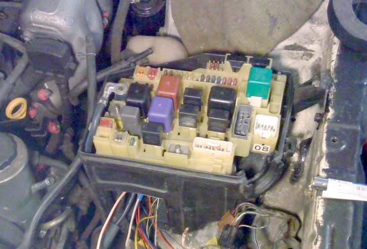
Diagram

Designation
| 1 | 7,5A TRC – VSC control unit |
| 2 | 7,5A ROOM LAMP 2 – Central locking, clock, trunk and interior lighting |
| 3 | 5A ALT SENCING – Generator |
| 4 | 20A EFI – Electronic engine control unit |
| 5 | 20A RADIO №1 – Radio tape recorder, multifunction display |
| 6 | 20A AM2 – Electronic engine control unit |
| 7 | 20A DOOR SUB – Central locking |
| 8 | 7,5A ELECTR2 – Air conditioning, cruise control, ABS, TRC and SRS |
| 9 | 7,5A ROOM LAMP – Interior lighting, front and rear |
| 10 | 15A HAZARD – Alarm |
| 11 | 15A TELEPHONE – Phone |
| 12 | 10A HORN – Sound signal |
| 13 | 15A HEAD (LH) – Left headlight |
| 14 | 15A HEAD (RH) – Right headlight |
| 15 | 7,5A REAR CON – Rear air conditioner |
| 16 | 5A l / UP – Engine Control Unit |
| 17 | 15A HEAD RH (HI) * 1 – Right headlight (high beam) |
| 5A l / UP 2 * 2 – Engine control unit | |
| 18 | 15A HEAD RH (HI) * 1 – Right headlight (high beam) |
| 19 | 30A FAN – Fan motor |
| 21 | 15A ETCS – Electronic Throttle Control |
Relay

- R1 – heater relay
- R2 – main relay of the injection system
- R3 – starter relay
- R4 – headlight relay
- R5 – air conditioning compressor clutch relay
- R6 – rear heater relay
- R7 – fuel pump relay
- R8 – main relay of the fan motor
- R9 – fan motor relay
Relay box

- R1 – relay of the electric pump ABS
- R2 – relay of electromagnetic pumps ABS
- R3 – relay of the electric pump TRC
- R4 – fuel pump relay
Type 2
Layout

Decoding
- intake air temperature sensor
- valve VVT
- throttle actuator motor (ETCS)
- throttle position sensor
- diagnostic connector DLC3
- ignition coil
- throttle sector (with sensor)
- electro pneumatic valve
- MAP sensor
- fuel vapor accumulator
- fuel pump
- rear oxygen sensor
- camshaft position sensor
- relay box No. 1
- switch
- knock sensor
- oxygen sensor B2S1
- fuse “AM” (50 A)
- nozzle
- oxygen sensor B1S1
- electronic engine control unit
- power steering pressure sensor
- coolant temperature sensor
- position sensor
- crankshaft knock sensor
- fuse “EFI” (25 A)
- fuse “ETCS” (15 A)
- fuel cut-off relay
- main relay of the injection system
- fuse ST 5 A
- fuse “IG” (15 A)
- fuse “EFI 2” (10 A)
- fuse “ALT” (120 A).
Photo example of the execution of blocks


Relay

Assignment
28380A RESISTER, FUEL PUMP
82741 BLOCK, ENGINE ROOM RELAY
89620 IGNITER ASSY
28371C RELAY, IGNITION, NO.2
85927 RELAY, COOLING FAN
89629 BRACKET, IGNITER ASSY
82660 BLOCK ASSY, RELAY, ENGINE ROOM
89438 SWITCH, POWER STEERING OIL PRESSURE
85927A RELAY, COOLING FAN, NO.2
82662B COVER, RELAY BLOCK, UPPER, NO.2
82602 BLOCK SUB-ASSY, RELAY
85912 RELAY, DEFOGGER
82742 BLOCK, ENGINE ROOM RELAY, NO.2
85941 RELAY, WINDSHIELD WASHER
89257 COMPUTER, COOLING FAN
82663 COVER, RELAY BLOCK, LOWER
85916P RELAY, HEADLAMP
82663A COVER, RELAY BLOCK, LOWER, NO.2
85926 RELAY, HEADLAMP DIMMER
85916D RELAY, FOG LAMP
89448A SENSOR, POWER STEERING OIL PRESSURE
85916F RELAY, CORNERING LAMP
86530 RELAY ASSY, HORN
85934 RELAY, MAGNET-CLUTCH
85941A RELAY, REAR WINDSHIELD WASHER
I’m looking for a toyota crown royal touring 1998 model fuse box.
I am looking for a Toyota Crown Royal Saloon 1996 Model Key Receiver Location? And Reverse Gear ⚙️ lighting no work