The 3rd generation Toyota Avalon was produced in 2005, 2006, 2007, 2008, 2009, 2010, 2011 and 2012 with the X30 designation. In this publication, we will show the locations of the electronic control units, a description of the fuses and relays of the Toyota Avalon 3 with box diagrams and photo examples and their execution. Highlight the cigarette lighter fuse.

The arrangement of the blocks and the purpose of the elements in them may differ from the one presented. Check the information with your diagrams on the box cover.
Contents
Passenger compartment
Location
Layout

Allocation
- Fuse box
- ECU for headlamp leveling
- Body ECU
- Remote control ECU
- Turn indicator
- Immobilizer code ECU (with Smart Key system) / Electronic key ECU (without Smart Key system)
- Driver side J / B
- Air conditioner control unit
- Air conditioner amplifier
- Passenger side J / B
- Engine control module
- Connector (CAN)
- Gateway ECU
- Smart key ECU
- Power supply control ECU
- Stereo component amplifier
- ECU for gearshift lock
- Airbag sensor assembly center
- Transponder Key Amplifier
- Steering lock ECU
Fuse box
It is located under the dashboard.

Example of a diagram from the block cover

Diagram

Assignment
| 1 | 25A RR DOOR – 2005-2009: Rear Right Passenger Window Regulator. |
| 1 | 20A RR DOOR – 2010-2012: Window Regulator (Right Rear Passenger). |
| 2 | 25A RL DOOR – 2005-2009: Rear Left Passenger Window Regulator. |
| 2 | 20A RL DOOR – 2010-2012: Power window (left rear passenger). |
| 3 | 25A FR DOOR – 2005-2009: Power window (front passenger), driver position memory system. |
| 3 | 20A FR DOOR – 2010-2012: Power window (front passenger), driver position memory system. |
| 4 | 15A FOG – Front fog lights |
| 5 | 7,5A OBD – On-board diagnostic system |
| 6 | 7,5A MPX-B – Multiplex communication system |
| 7 | – |
| 8 | 25A P / W – 2005-2009: Power widow, driver position memory system. |
| 8 | 20A FL DOOR – 2010-2012: Power window, driver position memory system. |
| 9 | 7,5A FUEL OPN – Fuel filler flap opener |
| 10 | 7.5A AM1 – Multiport fuel injection system / sequential multiport fuel injection system, starting system, ignition system |
| 11 | 7,5A A / C – Air Conditioning |
| 12 | 20A S-HTR – 2008-2012: Air Conditioning System. |
| 13 | 25A DOOR NO.2 – Multiplex communication system |
| 14 | 30A S / ROOF – Electric moon roof |
| 15 | 10A TAIL – Parking lights, license plate lights, rear lights, front and rear side marker lights |
| 16 | 7,5A PANEL – Heated seats, navigation system, hazard warning lights, electronically controlled automatic transmission, glove box lighting, instrument panel lights, sockets |
| 17 | 7.5A ECU IG NO.1 – 2005-2006: Center Display, Shift Lock Control System, Power Sunroof, Multiplex Communication System. |
| 17 | 10A ECU IG NO.1 – 2007-2012: Central display, shift lock control system, power sunroof, multiplex communication system, tire pressure monitoring (warning) system. |
| 18 | 7,5A ECU IG NO.2 – Anti-lock braking system, dynamic laser cruise control system, automatic headlight leveling system, vehicle stability control system, multiplex communication system |
| 19 | 7,5A HTR – Air conditioning system, instrument panel illumination, electric cooling fan |
| 20 | 7,5A A / C COMP – Air Conditioner |
| 21 | 20A S-HTR – 2005-2007: Air Conditioning System. |
| 22 | 10A GAUGE NO.1 – Reversing lights, navigation system, emergency flashers |
| 23 | 30A WIP – Wipers |
| 24 | 10A RR S / SHADE – Rear electric sun visor |
| 25 | Not used |
| 26 | 10A IGN – Multiport fuel injection system / sequential multiport fuel injection system, engine immobilizer system, SRS airbag system, front passenger classification system, smart key system, starter system |
| 27 | 7,5A GAUGE NO.2 – Manometers and counters, central display |
| 28 | 7.5A ECU-ACC – Power Mirrors, Center Display, Shift Lock System, Multiplex Communication System |
| 29 | 15A CIG – Cigarette lighter |
| 30 | 15A PWR OUTLET – Socket |
| 31 | 7,5A RADIO NO.2 – Audio system |
| 32 | 10A MIR HTR – Heated exterior mirrors |
The fuse number 29 at 15A is responsible for the operation of the cigarette lighter.
Some fuses and relays may be attached to the other side of the unit.
Diagram
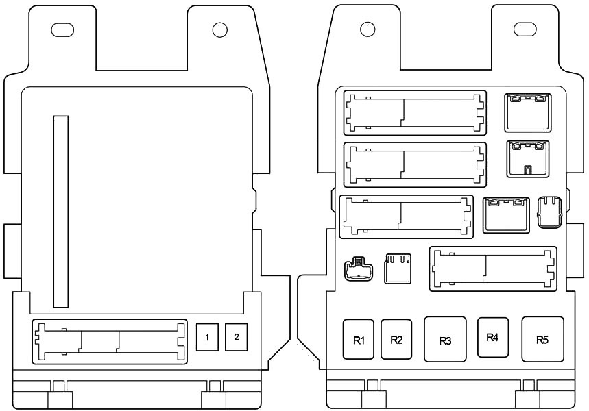
Designation
| 1 | 30A P / SEAT – Power Seats |
| 2 | 30A POWER – Electric windows |
| Relay | |
| R1 | Fog lights |
| R2 | Taillights |
| R3 | Auxiliary relay (ACC) |
| R4 | Power relay (PWR) |
| R5 | Ignition (IG1) |
Additional elements
Diagram

Appointment
- ECU for sliding roof system
- Outside mirror control ECU (right)
- Door control receiver
- Navigation ECU
- Rear sun visor relay
- Outside mirror control ECU (left)
Engine compartment
Location
Layout

Decoding
- Fuse and relay box
- Cooling fan ECU
- Driven skid control ECU
Fuse and relay box
Under the hood, the main fuse and relay box is installed on the left side next to the batteries.

Diagram
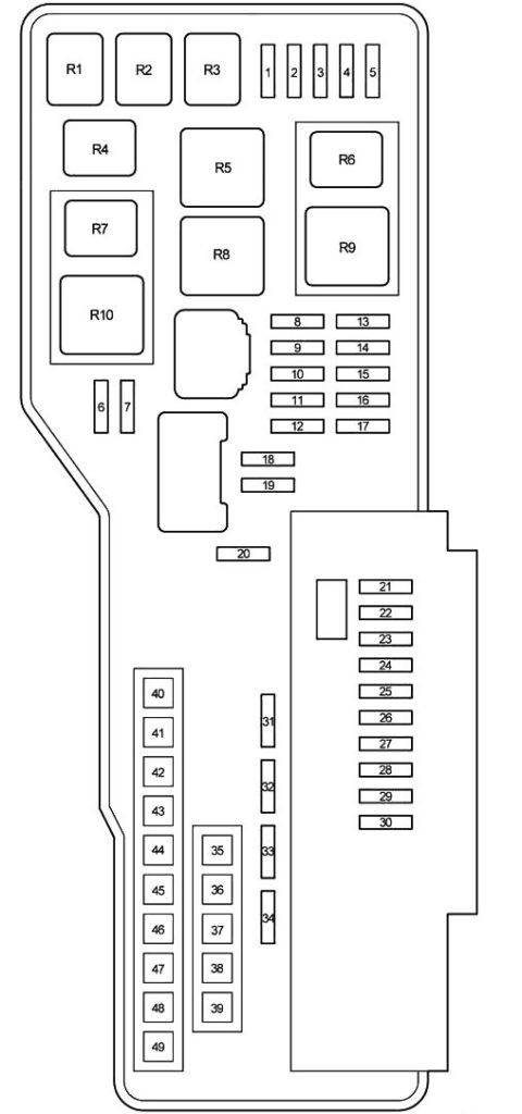
Designation
| 1 | 10A EFI NO.2 – Multiport fuel injection system / sequential multiport fuel injection system |
| 2 | 7,5A STOP NO.2 – Brake lights, high brake light, vehicle stabilization system, anti-lock braking system |
| 3 | 7,5A RADAR CC – 2005-2010: Vehicle stabilization system. |
| 4 | 15A HEAD RH LWR – Right headlight (low beam) |
| 5 | 15A HEAD LH LWR – Left headlight (low beam) |
| 6 | 7,5A STOP No.3 – 2008-2012: Electronically controlled transmission system, multiport fuel injection system / sequential multiport fuel injection system. |
| 7 | 15A INJ – Multiport fuel injection system / sequential multiport fuel injection system |
| 8 | – |
| 9 | 15A STOP NO.1 – Multiplex communication system |
| 10 | 25A STR LOCK – 2005-2010: Steering lock system. |
| 10 | 15A STR LOCK – 2011-2012: Steering lock. |
| 11 | 7.5A IMMOBI – 2005-2007: Engine immobilizer system, smart key system. |
| 11 | 7.5A EFI No.3 – 2008-2012: Smart Key System, Electronic Transmission Control System. |
| 12 | 30A AMP – Audio system |
| 13 | – |
| 14 | – |
| 15 | 15A RAD NO.1 – Audio system, central display, navigation system |
| 16 | 10A ECU-B – Central display, multiplex communication system |
| 17 | 7,5A DOME – Gauges and Meters, Clocks, Front Personal Lights, Door Lights, Garage Door Opener, Personal Rear Lights, Trunk Lights |
| 18 | 15A TURN / HAZ – Direction indicators |
| 19 | 25A IG2 – Multiport fuel injection system / sequential multiport fuel injection system |
| 20 | – |
| 21 | 7,5A S-HORN – Signal |
| 22 | 20A WASHER – Windshield washer |
| 23 | 25A A / F – Air-fuel ratio sensor |
| 24 | 15A HEAD RH UPR – Right headlight (high beam) |
| 25 | 15A HEAD LH UPR – Left headlight (high beam) |
| 26 | – |
| 27 | – |
| 28 | 10A HORN – Sound signal |
| 29 | – |
| 30 | 25A EFI NO.1 – Multiport fuel injection system / sequential multiport fuel injection system, fuel pump |
| 31 | 10A ETCS – Multiport fuel injection system / sequential multiport fuel injection system |
| 32 | 7,5A ALT-S – Charging system |
| 33 | 25A DOOR NO.1 – Multiplex communication system |
| 34 | 7,5A AM2 – Starter system |
| 35 | 120A ALT – Charging system, “RR DEF”, “ABS / VSC NO2”. Fuses “HEATER”, “ABS / VSC NO.1”, “RDI FAN”, “WASHER” and “S-HORN” |
| 35 | 140A ALT – Charging system, “RR DEF”, “ABS / VSC NO2”. Fuses “HEATER”, “ABS / VSC NO.1”, “RDI FAN”, “WASHER” and “S-HORN” |
| 36 | – |
| 37 | 40A MAIN – Headlights |
| 38 | – |
| 39 | 30A ST / AM2 – Starter system |
| 40 | 50A HEATER – Air conditioner |
| 41 | 50A ABS / VSC NO.1 – Anti-lock braking system, vehicle stability control system |
| 42 | 50A RDI FAN – Electric cooling fan |
| 43 | 30A ABS / VSC NO.2 – Anti-lock braking system, vehicle stability control system |
| 44 | 50A RR DEF – Heated rear window, heaters outside rearview mirrors |
| 45 | – |
| 46 | – |
| 47 | – |
| 48 | – |
| 49 | – |
| Relay | |
| R1 | ST – Starter |
| R2 | MG CLT – Air conditioning compressor clutch |
| R3 | IG2 – Ignition |
| R4 | BRK – Stop lights |
| R5 | RR DEF – Heated rear window |
| R6 | ST CUT – Starter |
| R7 | VSC NO.1 – Vehicle stability control |
| R8 | FAN NO.1 – Electric cooling fan |
| R9 | HEAD – Headlights |
| R10 | VSC NO.2 – Vehicle stability control |
We have posted a video on our YouTube channel. Watch and subscribe.
Diagrams, page layout, special notations and corresponding tech specifications are wonderful!! Ever so thankful to have found your site. Will certainly recommend to all weekend mechanics I know. Greatly appreciated!
I have a 2005 Avalon Ls that won’t turn nor won’t start.
All lights work outside and inside.
Radio works, windows and seats works.
No security system indicated when trying to start on dash.
I changed out relays under the hood fuse box and checked for blown fuse
I changed out starter and coil packs
WHY MY CAR WON’T START?
Is there a starter relay inside my car?