The 3rd generation Toyota Yaris was produced in 2011, 2012, 2013, 2014, 2015, 2016, 2017, 2018, 2019 and was designated as P130 / P150. Shipped all over the world. In some countries it is known under the names Toyota Echo, Toyota Vitz, Toyota Platz. In this article we will show the locations of all electronic control units, a description of the fuses and relays of the 3rd generation Toyota Yaris Vitz with box diagrams and their locations. Let’s highlight the fuse responsible for the cigarette lighter.

The arrangement of the boxes and the purpose of the elements in them may differ from that shown and depend on the year of manufacture, the level of equipment and the region of delivery. Verifies the information with its diagrams on the box cover.
Contents
Passenger compartment
Location
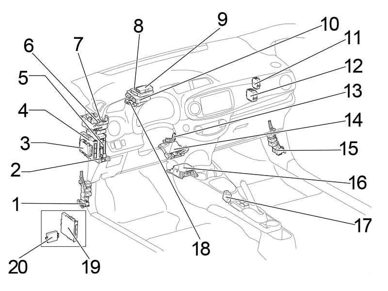
General layout of boxes in the cabin
LHD
RHD

Assignment
- Distribution block
- Fuse box
- Engine and transmission control unit (without start-stop system)
- Start-stop system control unit
- Body electrical control unit
- Heater relay (HTR)
- Relay box
- Driver assistance systems control unit
- Engine and transmission control unit (with start-stop system)
- Transmission control unit (LHD)
- Network gateway block
- Wiper relay
- Key transponder amplifier
- Air conditioner amplifier
- Distribution block
- Airbag control unit
- Selector lever lock control unit
- Power steering control unit
- Certification block
- Code ID block (with smart login and start system)
Key transponder control unit (without intelligent entry and start system)
Fuse box
It is located under the dashboard, covered with a protective cover.
LHD

RHD

Photo example of location

Diagram from the box cover

Diagram

Designation
| 1 | – |
| 2 | – |
| 3 | – |
| 4 | 15A S-HTR – Heated seats |
| 5 | – |
| 6 | – |
| 7 | 7,5A ECU-B NO.3 – Power mirrors |
| 8 | – |
| 9 | – |
| 10 | – |
| 11 | – |
| 12 | 25A D-D / L – Double blocking |
| 13 | – |
| 14 | – |
| 15 | 15A FOG FR – up to June 2013: Front fog light |
| 15A FOG FR – From June 2013 (TMC): Front Fog Light (TMC – Toyota Motor Corporation) | |
| 7,5A FOG FR – from June 2013 (TMMF): Front fog light (TMMF – Toyota Motor Manufacturing France) | |
| 16 | 7,5A AM1 – Starting system |
| 17 | 7,5A STOP – Multiport fuel injection system / sequential multiport fuel injection system, VSC, stop lamp, auxiliary stop light |
| 18 | 7,5A FOG RR – Rear fog light |
| 19 | – |
| 20 | 7.5 OBD – Diagnostic connector |
| 21 | 25A D / L – Central locking, body ECM |
| 22 | 5A ACC – Body ECM, Power Mirrors, Audio System, Gear Selector Lock |
| 23 | 15A CIG – Socket (cigarette lighter) |
| 24 | 20A DOOR – Window regulators |
| 25 | 20A DOOR R / L – Window regulators |
| 26 | 30A P / W – Power Windows |
| 27 | 15A WIPER RR – Rear wiper |
| 28 | 20A WIPER – Wiper |
| 29 | 15A WASHER – Washer for glass |
| 30 | – |
| 31 | – |
| 32 | 10A GAUGE – Reversing lamps, gear selector lock, audio system, charging system, multiport fuel injection system / sequential multiport fuel injection system |
| 33 | 7,5A A / C – Air conditioning, heated rear window, heated mirrors |
| 34 | 5A ECU-IG NO.2 – VSC |
| 35 | 5A ECU-IG NO.1 – Cooling Fan, Heated Rear Window, VSC, Electric Power Steering, Body Control Module, Wireless Control System, Tire Pressure Monitoring System |
| 36 | 20A DOOR P – Window regulators |
| 37 | 20A DOOR R / R – Window regulators |
| 38 | 5A PANEL – Instrument Cluster, Instrument Panel Light, Light Switch |
| 39 | 10A TAIL NO.2 – Side light, license plate light |
The fuse number 23, 15A, is responsible for the operation of the cigarette lighter.
Relay box
Diagram

Decoding
- R1 – Interior lighting (DOME CUT)
- R2 – until July. 2014: Front fog light (FR FOG) / from May 2015: (STP)
Additional elements
Scheme

Appointment
- Collision avoidance sensor
- Receiver for tire pressure monitoring system
- Audio amplifier
- Central locking receiver
Engine compartment
Location
General arrangement of blocks under the hood
LHD

RHD
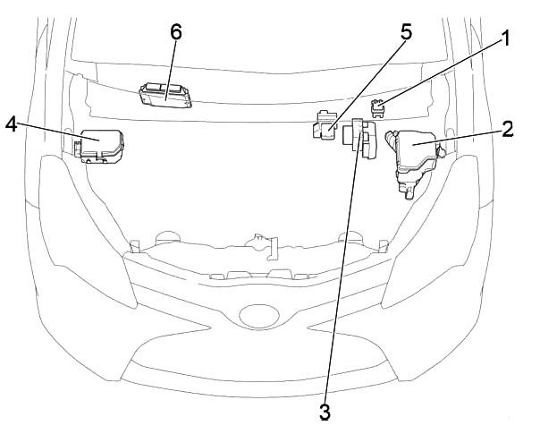
Assignment
- Glow plug relay
- Fuse and relay box
- Brake control unit
- Fuse box No. 2
- Power fuse box
- The engine control unit
Fuse and relay box
Photo – example

Diagram from the box cover

Diagram

Protected components
| 1 | 7,5A ID / UP – Multiport fuel injection system / sequential multiport fuel injection system |
| 2 | 20A EFI MAIN – Petrol: Multiport fuel injection system / sequential multiport fuel injection system |
| 30A ECD MAIN – Diesel: Multiport fuel injection system / sequential multiport fuel injection system | |
| 3 | 7,5A EFI NO.3 – Multiport fuel injection system / sequential multiport fuel injection system |
| 4 | 10A HORN – Sound signal |
| 5 | 10A EFI NO.2 – Multiport fuel injection system / sequential multiport fuel injection system |
| 6 | 10A IG2 – Multiport fuel injection system / sequential multiport fuel injection system, airbags, brake lights, front passenger classification system |
| 7 | 15A IGN – Multiport fuel injection system / sequential multiport fuel injection system |
| 8 | 7,5A MET – Instrument cluster |
| 9 | – |
| 10 | 30A PTC HTR NO.3 – from July 2014 (TMMF): Auxiliary heater (TMMF – Toyota Motor Manufacturing France) |
| 11 | 25A PWR HTR – before July 2014 (TMMF): Auxiliary heater (TMMF – Toyota Motor Manufacturing France) |
| 30A PTC HTR NO.2 – from July 2014 (TMMF): Auxiliary heater (TMMF – Toyota Motor Manufacturing France) | |
| 12 | 50A EPS – Electric power steering |
| 13 | 30A ABS NO.2 – ABS, VSC |
| 14 | 30A DEF – Heated rear window, heated mirrors |
| 15 | 40A HTR – Air Conditioning |
| 16 | 50A PTC HTR NO.1 – TMMF: Auxiliary heater (TMMF – Toyota Motor Manufacturing France) |
| 30A H-LP CLN – Headlight cleaner | |
| 17 | 30A RDI FAN – Cooling fan |
| 18 | 50A ABS NO.1 – ABS, VSC |
| 19 | 10A MIR-HTR – Heated Mirrors, Heated Rear Window, Cruise Control, Transmission Indicator, Engine Control Unit |
| 20 | 5A ECU-B NO.1 – Multiport fuel injection system / sequential multiport fuel injection system, body ECM |
| 21 | 15A DOME – Interior Lighting, Personal Lighting, Audio System, VSC |
| 22 | 40A BBC – Charging system (1NR-FE), start-stop system |
| 23 | 30A ST – Starting system |
| 24 | 15A AMP – TMMF: Audio system, navigation, parking assist (TMMF – Toyota Motor Manufacturing France) |
| 25 | 25A D / L NO.2 – until July. 2014: Double blocking |
| 25A PWR HTR – until July. 2014 (TMMF): Auxiliary heater (TMMF – Toyota Motor Manufacturing France) | |
| 26 | 30A D.C.C – Fuses: “DOME”, “ECU-B NO.1”, “ECU-B NO.2” |
| 27 | 20A STR LOCK – until July 2014 (TMMF): Trunk door, immobilizer, smart access system with start button, start system, steering lock, wireless control system (TMMF – Toyota Motor Manufacturing France) |
| 28 | 10A ETCS – Multiport fuel injection system / sequential multiport fuel injection system |
| 29 | 10A HAZ – Direction indicators, hazard warning lights |
| 30 | 7.5A AM2 – Multiport fuel injection system / sequential multiport fuel injection system, starting system |
| 31 | 5A ECU-B NO.2 – Instrument Cluster, Wireless Control System, Tire Pressure Monitoring System, Front Passenger Classification System |
| 32 | 7,5A ALT-S – Charging system |
| 33 | 50A R / I – Fuses: “EFI MAIN”, “EFI NO.2”, “EFI NO.3”, “IG2”, “IGN”, “MET”, “HORN” |
| 34 | 80A PTC – Auxiliary heater, heated mirrors |
| Relay | |
| R1 | Cooling fan (FAN NO.2) |
| R2 | Cooling fan (FAN NO.1) |
| R3 | Heated rear window (DEF) |
| R4 | Starter (ST) |
Fuse box №2

Diagram

Designation
| 1 | 20A ST NO.2 – Multiport fuel injection system / sequential multiport fuel injection system |
| 2 | 7,5A DRL – Daytime running lights |
| 15A EU-DRL – Daytime running lights | |
| 3 | 10A ECD NO.4 – Cooling fan, multiport fuel injection system / sequential multiport fuel injection system |
| 10A S-HORN – Multiport fuel injection system / sequential multiport fuel injection system | |
| 4 | 7,5A H-LP MAIN – before July 2014: Air conditioning, automatic lighting system, headlights, headlight range control |
| 20A H-LP MAIN – from July 2014: Air conditioning, automatic lighting system, headlights, headlight range control | |
| 5 | 50A MMT – Gearbox control unit |
| 6 | 10A H-LP RH HI – High beam right |
| 7 | 10A H-LP LH HI – High beam left, instrument cluster |
| 8 | 10A H-LP RH LO – Right low beam |
| 9 | 10A H-LP LH LO – Left low beam, front fog light |
| 10 | – |
| 11 | – |
| 12 | – |
| 13 | – |
| 14 | – |
| Relay | |
| R1 | before Jul 2014: Dimmer (DIM) (headlight switch) |
| from Jul 2014: Auxiliary heater (PTC HTR NO.1) | |
| R2 | Daytime running lights / anti-theft system (DRL / S-HORN) |
| R3 | Headlights (H-LP) |
| Headlights / Daytime Running Lights (H-LP / US-DRL) | |
Department №1
Diagram

Before July 2014
- R1 – Integrated relay
Since July 2014
- R1 Engine control unit (ECD NO.2)
- R2 Auxiliary heater (PTC HTR NO.2)
- R3 Auxiliary heater (PTC HTR NO.3)
- R4 Starter (ST NO.2)
Department №2
Diagram

Before July 2014
R2 – (O / P MTR (with Stop & Start System)) or R1 – Gearbox control unit (MMT)
Since July 2014
R1 – Dimmer (DIM (Projector Headlight))
Power fuse box
Located on the positive terminal of the battery.

Diagram

Circuits protected
- 80A GLOW DC / DC – Multiport fuel injection system / sequential multiport fuel injection system
- 80A MAIN – Fuses: “BBC”, “ST”, “AMP”, “D / L NO.2”, “DCC”, “STR LOCK”, “MIR-HTR”, “ETCS”, “HAZ”, ” AM2 “,” ALT-S “,” R / I “,” DRL “” EU-DRL “,” S-HORN “,” H-LP MAIN “,” H-LP RH HI “,” H-LP LH HI “,” H-LP RH LO “,” H-LP LH LO “
- ALT 120A – Charging system, Fuses: “ID / UP”, “EPS”, “ABS NO.2”, “DEF”, “PTC”, “HTR”, “H-LP CLN”, “RDI FAN”, ” ABS NO.1 “,” TAIL NO.2 “,” PANEL “,” DOOR R / R “,” DOOR P “,” ECU-IG NO.1 “,” ECU-IG NO.2 “,” A / C “,” GAUGE “,” WASHER “,” WIPER “,” WIPER RR “,” P / W “,” DOOR R / L “,” DOOR “,” CIG “,” ACC “,” D / L ” , “OBD”, “STOP”, “AM1”, “FOG FR”
Check out our YouTube video for more on this topic. Don’t forget to subscribe!
where is the indicator relay located in the RHD YARIS
Merci beaucoup pour le programme