The 1st generation Peugeot Expert was produced in 1995, 1996, 1997, 1998, 1999, 2000, 2001, 2002, 2003 and 2004. During this time, the model has been restyled. In this article we will show a description of the Peugeot Expert 1 fuses and relays with box diagrams and their locations.

Contents
Passenger compartment
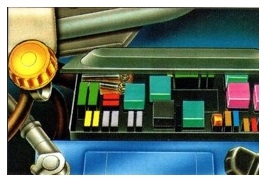
In the passenger compartment, the main fuse box is located on the lower left side of the instrument panel.
Box access example
LHD

RHD

Type 1
Diagram

Assignment
- 10 A Car radio (power supply)
- 5 A + after ignition feed – Speed sensor – Central protection unit – Instrument panel warning lights
- 15 A Brake light – Cruise control
- 10 A Right rear light – Left front side light – Headlamp adjustment
- 15 A Air conditioning – Front power windows – Air conditioning blower – Pressure sensor
- 15 A Rear heated glass and heated seats
- 20 A Buzzer
- SHUNT –
- 5 A Headlamp washers – Front right side light – Number plate light – Left rear light
- 30 A Adjusting the front passenger seat
- 30 A Rear power windows
- 10 A ABS computer – Reversing lights – Diagnostic connector – Automatic transmission
- 30 A Driver’s seat adjustment
- 5 A Central protection unit for passenger compartment (memory)
- 30 A Central protection unit for passenger compartment – Electric central locking – Lights
- 20 A Cigarette lighter – Permanent (+) from the storage battery – (+) drive of additional electricity consumers
- 15 A Coolant temperature control unit – Engine cooling fan group
- 10 A Fog lamp
- 10 A Instrument panel lighting – Car radio – Side lights
- 30 A Air conditioning – Air conditioner fan
- 20 A Heated seats
- 20 A + Power supply of additional electricity consumers – Not used
- SHUNT F14 – F15 – F25 – F27
- 30 A Windscreen washer – Front windscreen wiper
- 10 A Air conditioning – Dome – Car radio memory – Digital clock
- 15 A Hazard lights
- 30 A Heated rear window
- 15 A Power windows – Low battery warning lamp
- 30 A Power windows
- 15 A Interior lighting – Indicator lights – Clock – Exterior mirrors, electrically adjustable
The fuse number 16, 20A, is responsible for the cigarette lighter.
Type 2
Diagram

Designation
| 1 | Not used. |
| 2 | 10A Diagnostic socket – ABS control unit – Reversing lights – Heated mirrors. |
| 3 | Not used. |
| 4 | 5A Instrument panel – overspeed buzzer – speed sensor – diesel filter water sensor. |
| 5 | 15A Cruise control – Brake switch – Clutch switch – Automatic transmission – Brake lights. |
| 6 | 5A Backlight – Instrument panel – Audio. |
| 7 | 30A Heated rear window. |
| 8 | 30A Interior protection unit. |
| 9 | 5A Interior protection unit. |
| 10 | Not used. |
| 11 | 5A Fan relay assy – compressor relay. |
| 12 | 10A Electric windows – Fan relay – Seat heating relay – Heated rear window switch – Air conditioning – Pressostat. |
| 13 | 15A Signal lights. |
| 14 | 30A Electric windows. |
| 15 | Not used. |
| 16 | 20A Heated seats. |
| 17 | 20A Signal |
| 18 | 10A Rear fog lamp. |
| 19 | 5A Cruise control – Buzzer lighting – Heated seat switch – Dashboard lighting – Audio – Heated rear window switch – Automatic transmission lever – Hazard switch – Air conditioning control panel. |
| 20 | 5A Headlamp leveling switch – Front left and front right side lights. |
| 21 | 5A Rear left and right rear parking lights – Headlight washer timer – License plate light. |
| 22 | Not used. |
| 23 | 20A Lighting |
| 24 | 10A Audio equipment. |
| 25 | 10A Buzzer illumination – Automatic transmission buzzer – Power mirrors – Direction indicators. |
| 26 | 30A Wiper timer – Windscreen wipers – Washer pump. |
| 27 | Not used. |
| 28 | 5A Instrument panel – power window relay. |
The fuse number 23 is responsible for the cigarette lighter.
Engine compartment
Under the hood, the main fuse and relay box is next to the battery.
Type 1
Without ABS

Diagram

Diagram

Appointment
| F1 | 20A Fuel pump |
| F2 | 10A Right low beam |
| F3 | 10A Left low beam |
| F4 | 25A Headlight washer |
| F5 | Shnut |
| F6 | 10A Electronic anti-theft device |
| F7 | 10A Catalytic converter sensor |
| F8 | 20A Trailer |
| F9 | 25A Cooling fan unit 1 – 120W |
| F9 | 30A Cooling fan unit 1 – 180W |
| F10 | 15A Reserve |
| F11 | 5A Reserve |
| F12 | 10A Left high beam |
| F13 | 10A Right high beam |
With ABS
Diagram

Decoding
- 20 A Residential trailer
- 20 A Fuel pump
- 10 A Left low beam headlamp
- 10 A Right-hand dipped beam headlamp
- 10 A Diagnostic socket
- 10 A Engine immobilizer
- 10 A Left high beam headlamp
- 10 A Right high beam headlamp
- 25 A Motor cooling fan group 1-120 W.
- 30A Headlight washer pump, fog lights
- 20 A Additional heating system
- 5 A Headlight washer timer
- 15 A Catalytic converter oxygen sensor, lambda probe heating
- –
- 40 A Air conditioning, passenger compartment fan
- 30 – 50 A Motor cooling fan group 1 – 180 W.
MF1 20A – Injection system relay, MF2 30A – Injection system relay, MF3 30A – Interior blower, MF4 40A – ABS computer.
Fuses not marked with numbers are spare.
Relay

Designation
- R 1030 – Information about a running engine
- R 1502/1503/1504 – Relays for fans
- R 5400 – Headlight washer relay
- R 8016 – Injection relay
- R 2665 – Fog lamp relay
Type 2
Diagram

Assignment
| 1 | 20A Fuel pump |
| 2 | 10A Right low beam headlamp |
| 3 | 10A Left low beam headlamp |
| 4 | 25A Headlight washer |
| 5 | Shunt |
| 6 | 10A Engine Immobilizer |
| 7 | 10A Catalytic converter sensor |
| 8 | 20A Tow bar |
| 9 | 25A Fan unit with a capacity of 1-120 W |
| 9 | 30A Fan unit with a capacity of 1-180 W |
| 10 | 15A Fog lights |
| 11 | Not used |
| 12 | 10A Left high beam |
| 13 | 10A Right high beam |
| MF1 | 70A Engine run relay |
| MF2 | 70A ABS control unit – Ignition switch |
| MF3 | 30A Blower – Air Conditioning |
| MF4 | 30A Fan assy |
Hi,
I have a 2000 Peugeot Expert, 1.9, no turbo. Do you have the schematic and images for the Green (12v-25A-03601) relay and the Blue one to the right of that. The Green one is for my heater fan and the Blue one is for the intermittent wiper control. Both tend to lose connection as the matrix that hold them into the female receiver is loose..cant see where it was originally fastened…very awkward location. any info you have on these relays would be appreciated.
Thanks,
Roger
Terima kasih…atas informasinya
Where is the indicator relay , Expert 2004?