Peugeot Bipper compact mini van went on sale in 2009. Released in 2010, 2011, 2012, 2013, 2014, 2015, 2016, 2017, 2018. We will show the location of blocks with fuses and relays of the Peugeot Bipper and their purpose and photo examples of execution. Let’s highlight the cigarette lighter fuse.

The purpose of fuses and relays may differ from those presented and depend on the year of manufacture and the level of electrical equipment of your car.
Passenger compartment
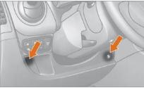
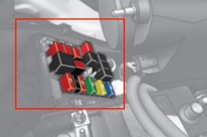
Inside the car, the fuse box is located at the bottom of the instrument panel. To access the fuse box, you need to remove two screws using the ignition key and lower the block.
photo

Diagram

Assignment
- F12 7.5A Right-hand dipped beam headlamp.
- F13 7.5 A Left low-beam headlamp, headlight range control.
- F31 5 A Engine ECU power switch.
- F32 7.5 A Head light, front light, rear light switch on.
- F36 10 A Car radio, mobile phone circuit, air conditioning control panel, EOBD diagnostic connector.
- F37 5 A Brake light, instrument cluster.
- F38 20 A Door locks.
- F43 15 A Washer pump.
- F47 20 A Driver’s door window regulator.
- F48 20A Passenger door window regulator.
- F49 5 A Parktronic ECU, rear light switch, exterior mirrors, interior control sensor.
- F50 7.5 A Airbag computer.
- F51 7.5 A Brake light contactor, clutch pedal contactor, door mirror control panel, Bluetooth system.
- F53 5 A Instrument cluster, rear fog lamps.
- F41 7.5 A Heated exterior mirrors.
- F94 15 A Cigarette lighter.
- F96 15 A 12V socket.
- F97 10 A Heated driver’s seat.
- F98 10 A Heated passenger seat.
The fuses number 94 and 96 at 15A are responsible for the cigarette lighter and the socket.
Engine compartment
The underhood fuse and relay box is located in the front of the engine compartment. To get to the box you need to disconnect the connector block from the front left headlight and only then move on to the cover latches.
Photo

Diagram

Designation
| 1 | 60A Embedded Systems Interface Supply |
| 2 | No |
| 3 | 20A Starter |
| Supply | |
| 4 | 40A ABS pump |
| 5 | No |
| 6 | 20A Single Speed Cooling Fan |
| 7 | 40A Cooling Fan, High Speed |
| 8 | 30A Air conditioner |
| 9 | 15A trailer |
| or missing | |
| 10 | 15A Horn |
| 11 | 10A Engine control unit |
| 14 | 15A Headlights |
| 15 | No |
| 16 | No |
| 17 | 7.5A Fuel filter |
| or – | |
| 18 | 7.5A Main relay |
| 19 | 7.5A Air conditioning compressor |
| 20 | 30A Heated rear window |
| Heated mirrors | |
| 21 | No |
| 22 | 15A Injection pump |
| or – | |
| 23 | 20A Fuse and relay box in the engine compartment |
| 24 | 7.5A ABS control unit |
| 30 | 15A Fog lights |
| 81 | 60A Heating control unit |
| or not used | |
| 82 | No |
| 84 | No |
| 85 | 15A Cigarette Lighter and 12V Socket |
| Heated seats | |
| 87 | 7.5A Reversing lights |
| Water in fuel sensor | |
| T02 | High beam relay |
| T03 | Signal relay |
| T05 | A/C compressor relay |
| T06 | Cooling fan relay |
| T07 | Two-speed cooling fan |
| T08 | Air Conditioning Fan Motor |
| T09 | Engine control unit, main relay |
| T10 | Fuel pump relay |
| Auxiliary relay, fuel pump | |
| T14 | Fog light relay |
| T17 | No |
| T19 | Heated rear windshield relay |
| Heated mirror | |
| T20 | Starter Interlock Relay |
| T30 | No |
| T31 | Socket |
| Lighting | |
| Relay, heated seats |
The fuse number 85 at 30A is still responsible for the cigarette lighter.
Check out our YouTube video for more on this topic. Don’t forget to subscribe!
If you have anything to add, write in the comments.
Hi there I have a electrical problem with my peugeot bipper tepee 1.3 cdti do you have a complete wiring diagram for this model and if yes could I purchase a copy I need it to fault find and have searched the Internet without any success many thanks Chris
My glow plugs not got no power going to them witch telling me it’s rely now would it be rely for that in the fuse box under the bonnet or would it be on the engine it’s self
Do you have a diagram to help me identify the relay that operates the immobilizer on a 2011 Peugeot Bipper