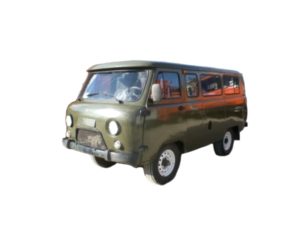
UAZ 2206 is the name of a family of all-wheel drive cargo and passenger off-road vehicles produced in various modifications since 1965 (UAZ 452, 3741, 3909, 39094, 3962, 3303, 3741), mainly with gasoline engines (injector and carburetor). In this article, we will show the wiring diagram, an assignment of the fuses and relays of the Uaz 2206 and their location.

Wiring diagram

Assignment
| 1 | front lamp; |
| 2 | headlight; |
| 3 | special sign lantern (only for UAZ-3962); |
| 4 | heater fan electric motor (only for UAZ-3962, UAZ-2206); |
| 5 | sensor of the signal lamp of the emergency state of the hydraulic drive of brakes; |
| 6 | sound signal; |
| 7 | side turn signal repeater; |
| 8 | reversible headlamp (only for UAZ – 3962); |
| 9 | headlight switch; |
| 10 | cabin lighting plafond; |
| 11 | signal lamp for turning on the parking brake system; |
| 12 | parking brake warning light switch; |
| 13 | wiper motor; |
| 14 | wiper and washer motor switch; |
| 15 | speedometer; |
| 16 | signal lamp for turning on the high beam headlights; |
| 17 | voltmeter; |
| 18 | oil pressure indicator; |
| 19 | warning lamp for emergency oil pressure; |
| 20 | coolant temperature gauge in the engine block; |
| 21 | warning lamp for emergency overheating of the coolant in the radiator; |
| 22 | fuel level indicator; |
| 23 | washer motor; |
| 24 | alarm switch; |
| 25 | signal lamp for direction indicators; |
| 26 | warning lamp for the emergency state of the hydraulic drive of the brake system; |
| 27 | ignition switch; |
| 28 | central light switch; |
| 29 | thermal fuse; |
| 30 | heater resistance; |
| 31 | heater fan motor switch; |
| 32 | headlight switch; |
| 33 | rear fog lamp switch; |
| 34 | fuse box; |
| 35 | plug socket; |
| 36 | unbalance solenoid valve; |
| 37 | turn signal switch; |
| 38 | horn button; |
| 39 | oil pressure warning light sensor; |
| 40 | sensor for the warning lamp for emergency overheating of the coolant in the radiator; |
| 41 | oil pressure gauge sensor; |
| 42 | coolant temperature gauge sensor in the cylinder block; |
| 43 | turn signal interrupter; |
| 44 | heater fuse (only for UAZ-3962, UAZ-2206); |
| 45 | heater fan motor switch (only for UAZ-3962, UAZ-2206); |
| 46 | resistance of the heater fan motor switch (only for UAZ-3962, UAZ-2206); |
| 47 | heater fan electric motor (only for UAZ-3962, UAZ-2206); |
| 48 | generator; |
| 49 | spark plug; |
| 50 | sensor-distributor; |
| 51 | ignition coil; |
| 52 | power switch; |
| 53 | rechargeable battery; |
| 54 | light switch; |
| 55 | plug socket (only for UAZ-3962, UAZ-2206); |
| 56 | plafond; |
| 57 | transistor switch; |
| 58 | emergency vibrator; |
| 59 | electronic control unit for the carburetor; |
| 60 | microswitch; |
| 61 | additional resistance; |
| 62 | additional starter relay; |
| 63 | solenoid valve; |
| 64 | starter; |
| 65 | fuel level indicator sensor in the tank; |
| 66 | brake signal switch; |
| 67 | reversing light switch; |
| 68 | back lamp; |
| 69 | rear fog lamp; |
| 70 | license plate light; |
| 71 | reversing light; |
| 72 | trailer socket |
Fuses and relays
Layout

Designation
- fuse box;
- turn signal interrupter;
- ABS lamp control relay;
- high beam relay;
- low beam relay;
- wiper breaker;
- rear fog lamp relay;
- starter relay.
The rear fog lamp relay 7 is located on the extension of the front panel rail under the dashboard in the area where the right headlight is located.
In the area of the brake pedal bracket there are a wiper switch 6, a high beam relay 4, a low beam relay 5.
The fuse box is mounted on the left under the dashboard and has three separate inserts.
Diagram

Appointment
For cars with ZMZ-4091 Euro-3 engine.
F1 10 Amp, Pin I – Warning Lamp Block, Hazard Alarm, Speedometer, Instrument Cluster, ABS sensors, if installed on the vehicle.
F1 10 Amp Pin II – Reserved.
F2 10 Amp Pin III – Alarm, buzzer.
F2 10 Amp Pin IV – Recirculation Pump, Heater Switch, Reverse Light Switch.
F3 10 Amp Pin V – Integrated Microprocessor Engine Control System, Ignition Switch.
F3 10 ampere, pin VI – Ignition switch, thermo-bimetallic fuse.
For cars with ZMZ-40911 Euro-4 engine.
F1 10 Amp, Pin I – Warning Lamp Block, Hazard Alarm, Speedometer, Instrument Cluster, ABS sensors, if installed on the vehicle.
F1 10 Amp Pin II – Reserved.
F2 10 Amp Pin III – Direction Indicator Switch, Hazard Alarm, Power Socket.
F2 10 Amp Pin IV – Recirculation Pump, Heater Switch, Reverse Light Switch.
F3 10 Amp Pin V – Integrated Microprocessor Engine Control System, Ignition Switch.
F3 10 ampere, pin VI – Ignition switch, thermo-bimetallic fuse.
The ABS fuses are located on the bulkhead behind the driver’s seat at either 25A or 40A.

This concludes the article. And if you want to help supplement the material, write everything in the comments.
 FuseAndRelay.com