Chery Tiggo 7 Pro is 2 generations of Chery Tiggo 7 that were released in 2020, 2021, 2022, 2023, 2024. An improved version of the model is called Tiggo 7 Plus. Also known as DR Motor DR F35 in some countries. In our material you can find a description of the fuses and relays Chery Tiggo 7 with fuse box diagram diagrams, their locations and photo examples of execution. detection of the safety function of the cigarette lighter.

Passenger compartment
In the passenger compartment, the fuse and relay box is located at the bottom of the instrument panel behind a plastic protective cover.

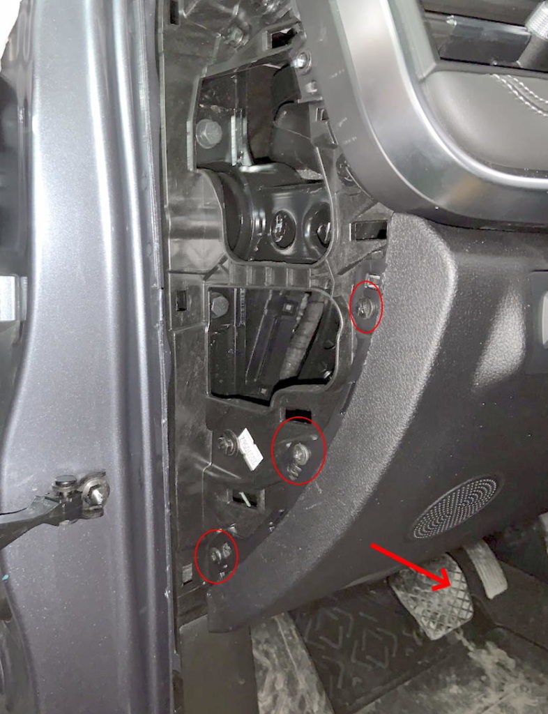
To gain access to it, you need to remove the door seal near the panel. Next, remove the cover from the left end of the instrument panel. We hook it into the hole for a screwdriver and remove the cover. Unscrew the 3 screws with a cross screwdriver. Then, on the right, we pull a large pad under the steering column, and on the left, we remove it from the hooks. Assemble in reverse order. Do not forget to disconnect 2 connectors, one for the speaker and the other for the buttons.
The block itself will look something like this.

Diagram

Assignment
| RF01 | 10A Comfort Unit, Dashboard/Instrument Cluster Control Unit, Immobilizer (BCM & ICM & IMMO) |
| RF02 | Reserve |
| RF03 | 10A Steering Angle Sensor, EPS (EPS & SAM) |
| RF04 | 10A Blank or some options -360 Surround Vision System, Blind Spot Monitor, Multimedia System, Vehicle Proximity Warning Radar (AVM & BSD & MPC & MRR) |
| RF05 | 10A Airbags, system control unit (AIR BAG) |
| RF06 | Reserve |
| RF07 | 10A A/C control panel, head unit control panel, power headlight adjustment switch, ESP control switch (SEE NOTE) |
| RF08 | Reserve |
| RF09 | 10A Radio, head unit control unit, air conditioning and heater control panel (RADIO & AC & T-BOX) |
| RF10 | Front panel control unit, rain sensor (ICM & Rain Sensor) |
| RF11 | Reserve |
| RF12 | Reserve |
| RF13 | Reserve |
| RF14 | Reserve |
| RF15 | 7,5A Sunroof, Volume control, Key illumination, Monitor module, Heating relay coil (DIAGNOSIS & VTM & KEYIN & EPB SW) |
| RF16 | 10A USB charger, usb port (USB POWER) |
| RF17 | Reserve |
| RF18 | 10A Heated side mirrors with electric adjustment (left and right), Feedback of the operation of the heated / heated rear window (MIRROR HEATER) |
| RF19 | 10A PEPS keyless entry and start system, 4WD system, ECU and DC-DC (ISS) start-stop system (PEPS&DC(ISS)) |
| RF20 | 30A Seat adjustment, electric (SEAT ADJ) |
| RF21 | 10A AM2 circuit at engine start (on vehicles without PEPS keyless entry system) (IGN SW2) |
| RF22 | 20A Empty or ignition position 1 (IGN SW1) |
| RF23 | Reserve |
| RF24 | 30A Heated rear window, relay 03 (DEFROST) |
| RF25 | Reserve |
| RF26 | 10A Control block head unit, electric mirror adjustment, BCM unit, (RADIO & BCM & MIRROR ADJ) |
| RF27 | 15A Cigar lighter (CIGAR LIGHT) |
| RF28 | 15A Reverse Lamp |
| Relay | |
| RRLY 01 | Reserve |
| RRLY 02 | Reversing lamp for ISS (Reverse Lamp for ISS) |
| RRLY 03 | Heated rear window relay (DEFROST) |
The fuse 27 to 15A is responsible for the cigarette lighter.
Engine compartment
Under the hood, the main fuse and relay box is located on the left side, next to the battery, and is covered with a protective cover.
Photo example

Check the purpose of the elements with your diagrams on the cover of the blocks.
An example of a circuit from the box cover

Diagram

Designation
| EF01 | 20A Heated / heated seats (SEAT HEAT) |
| EF02 | 15A Electronic Steering Column Lock (ESCL) |
| EF03 | 10A High beam – left headlight, power supply (L HIGH BEAM) |
| EF04 | 10A High beam – right headlight, power supply (R HIGH BEAM) |
| EF05 | 15A IGN1 ignition power (IGN POWER) |
| EF06 | 7.5A Dynamic Stability Control and ABS Brake System (ESP/ABS) |
| EF07 | 7.5A ECU, transmission control unit, brake light switch and conc. off reverse gear (ECU & TCU & Brake SW) |
| EF08 | 10A A/C Compressor Tube Pressure Switch and Parking Assist Control Module (AC SW & Radar) |
| EF09 | 7.5A Generator field winding (ALT EXC) |
| EF10 | 25A BCM comfort unit – power 5 (BCM POWER5) |
| EF11 | 25A BCM comfort unit – power 6 (BCM POWER6) |
| EF12 | 20A On Relay 16 – vacuum pump relay (VACUUM PUMP) |
| EF13 | 15A Heated oxygen sensors, front and rear (O2 SNSR) |
| EF14 | 15A Ignition coil (IGN COIL) |
| EF15 | 15A Memory Fuse |
| EF16 | 25A Comfort unit BCM – Power 4 (Power4) |
| EF17 | 30A Sunroof (SUNROOF) |
| EF18 | 25A BCM – Power 5 (Power5) |
| EF19 | 10A On relay 10 – transmission control relay, TCU unit (TCU) |
| EF20 | 15A Fog lights (ptf), relay 17 (FOG Lamp) |
| EF21 | 20A Comfort unit BCM – Power 3 (Power3) |
| EF22 | 10A At Relay 11 – Horn, Relay 04 – Low Beam, Relay 02 – High Beam, Relay 05 – Engine Management System EMS (COIL) |
| EF23 | 25A Comfort unit BCM – Power 6 (Power6) |
| EF24 | 10A Brake lights |
| EF25 | 15A Signal (beep, klaxon) (HORN) |
| EF26 | 7.5/10A Engine control unit ECU and transmission control unit TCU (ECU/TCU) |
| EF27 | Washer |
| EF28 | 10A Reversing lights, relay 07 (REVERSE) |
| EF29 | 30A Wipers and washer (on relay 08 – low speed wiper and relay 09 – high speed wiper) (WIPER) |
| EF30 | 10A A/C Compressor Clutch Relay 12 (AC Clutch) |
| EF31 | 15A Fuel pump (fuel pump) (FUEL PUMP) |
| EF32 | Spare fuse box |
| EF33 | 15A Dipped beam – left headlight (L LOW BEAM) |
| EF34 | 15A Dipped beam – right headlight (R LOW BEAM) |
| EF35 | 15A Electric thermostat, VVT valve control system, EGR valve, fuel vapor canister valve (VALVE) |
| EF36 | 10A Adaptive transmission control system (some models) (AGS) |
| EF37 | 7.5/10A ECU – Electronic Engine Control Unit (ECU) |
| EF38 | 15A Cylinder 1, 2, 3, 4 injectors (INJECTOR) |
| EF39 | Empty |
| EF40 | 7,5A Air conditioning stove fan, relay 15 (BLOWER RLY Coil) |
| SB01 | 25/40A Dynamic Stability Control and ABS Brake System (ESP/ABS) |
| SB02 | 30A BCM comfort unit – power supply 2 (BCM Power2) |
| SB03 | 30A Robotic Transmission (DCT) |
| SB04 | 30A BCM comfort unit – power supply 1 (BCM Power1) |
| SB05 | 50A Heated windshield/windshield (Windshield Heat2) |
| SB06 | 30A Stove fan, interior heater and air conditioner, on relay 15 (BLOWER) |
| SB07 | 30A Starter (START) |
| SB08 | 40A Dynamic Stability Control and ABS Brake System (ESP/ABS) |
| SB09 | 30A Accessories (ACC) |
| Relay | |
| ERLY 01 | Accessories (ACC) |
| ERLY 02 | High Beam Relay (HIGH BEAM) |
| ERLY 03 | Ignition (IGN) |
| ERLY 04 | Low Beam Relay (LOW BEAM) |
| ERLY 05 | Engine management system (EMS) |
| ERLY 06 | Vacuum pump (VACUUM PUMP) |
| ERLY 07 | Reversing lights (REVERSE LAMP) |
| ERLY 08 | Low speed wipers (wiper) (WIPER LOW) |
| ERLY 09 | High speed wipers (wiper) (WIPER HIGH) |
| ERLY 10 | Transmission control unit (TCU) relay |
| ERLY 11 | Signal (HORN) |
| ERLY 12 | Air Conditioning Compressor Electromagnetic Clutch (AC Clutch) |
| ERLY 13 | Fuel pump relay (fuel pump) (FUEL PUMP) |
| ERLY 14 | High fan speed radiator (engine cooling system) (FAN HIGH) |
| ERLY 15 | Stove / heater fan (BLOWER) |
| ERLY 16 | Starter (START) |
| ERLY 17 | Fog lights (PTF) (FOG Lamp) |
| ERLY 18 | Low fan speed radiator (engine cooling system) (FAN LOW) |
The group of high power power fuses is installed in the lower part of the unit.
Diagram

Appointment
- 150A – Generator
- 40A – Low speed radiator fan (engine cooling system)
- 50A – High speed radiator fan (engine cooling system)
- 80A – Electric power steering EUR (EPS)
- 60A – Fuse box in the cabin
Found a mistake or have something to add – write in the comments.