Nissan Xterra 2 generation was produced in 2005, 2006, 2007, 2008, 2009, 2010, 2011, 2012, 2013, 2014, 2015. During this time, the model received a facelift. In this post you can find a description of the fuses and relays Nissan Xterra 2G with fuse box diagrams, their locations and photo examples of execution. Note the fuse responsible for the cigarette lighter.

Purpose of fuses and relays may differ from that described here and depends on the year of manufacture and the level of electrical equipment in your vehicle.
Contents
Passenger compartment
The fuse box is located behind the lid in the glove compartment. Open the glove compartment and pull the fuse box cover to remove it.

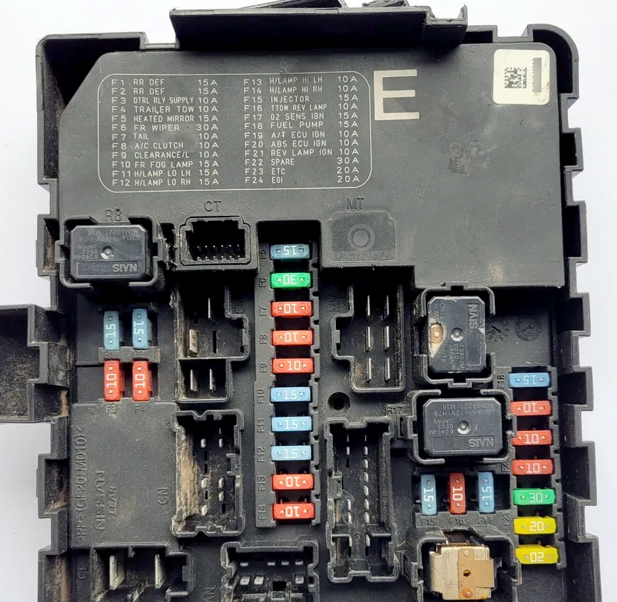
Photo for example

Check the actual description with yours on the back side of the protective cover.

Diagram
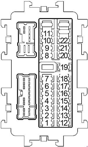
Assignment
| 1 | 10A BCM (Body Control Module), ECM (Engine Control Module) |
| 2 | – |
| 3 | 10A Differential Lock Control Unit, Differential Lock Mode Switch |
| 4 | 10A Audio, BCM (Body Control Module), Satellite Radio Tuner |
| 5 | 20A ’10-’15: Power Socket |
| 15A ’04-’09: Console Power Socket | |
| 6 | 10A Door Mirror Remote Control Switch |
| 7 | 15A ’04-’09: Upper Front Power Socket |
| 8 | 10A ’10-’15 Front Air Control, Front Blower Motor Relay |
| 9 | 15A Backdoor lock module |
| 10 | 15A ’10-’15 Electronic air conditioning control unit, electric drive for changing the air flow direction flap |
| 11 | 15A ’10-’15 Electronic air conditioning control unit, electric drive for changing the air flow direction flap |
| 12 | 10A ASCD Brake Switch, Heated Seat Relay, Data Link Connector, Stop Lamp Swicth, Sonar System, Automatic Transmission Control System, Audio |
| 13 | 10A Air Bag Diagnosis Sensor Unit, Occupant Classification System Control Unit |
| 14 | 10A Combination Meter, Auto Anti-Dazzling Inside Mirror |
| 15 | 10A Combination Switch |
| 16 | 10A Heated Seat Relay |
| 17 | 15A Audio Amplifier, Satellite Radio Tuner |
| 18 | 10A BCM (Body Control Module), Cargo Lamp Relay, Front Room/Map Lamp, Ignition Keyhole Illumination, Room Lamp 2-nd Row, Brake Control System, 4WD |
| 19 | 10A Auto Anti-Dazzling Inside Mirror, Combination Meter, Data Link Connector, Differential Lock Control Unit, Front Air Control, Tire Pressure Monitoring System |
| 20 | 10A Stop Lamp Relay, Stop Lamp Switch |
| 21 | 10A Steering Angle Sensor, Transfer Control Unit, BCM (Body Control Module), Interior Room Lamp, Power Door Lock System, NVIS, Vehicle Security System |
| 22 | 10A Automatic Transmission Assembly |
Fuse number 5 is responsible for the cigarette lighter.
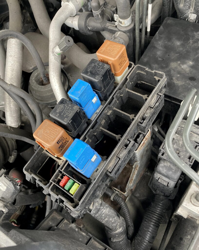
An accessory relay is attached to the back of the unit
Engine compartment
Under the hood, in the engine compartment of the car, on the left side, next to the battery, there are 3 blocks with fuses and relays.

Fuse and Relay Box
Type 1
Diagram from covery

Diagram
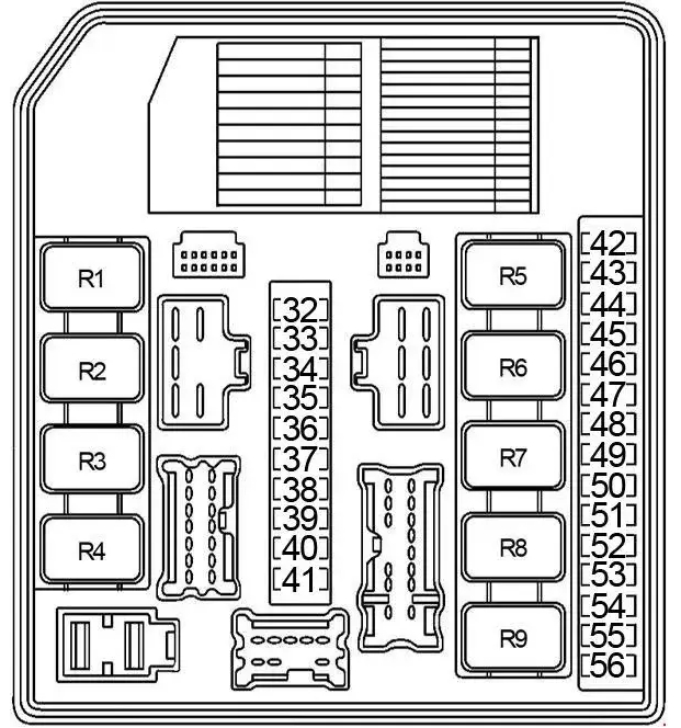
Designation
| 32 | 10A Trailer Tow Relay 2 |
| 33 | – |
| 34 | 10A Headlamp RH (High) |
| 35 | 10A Headlamp LH (High) |
| 36 | 10A Front Combination Lamps |
| 37 | 10A Rear Combination Lamps, License Plate Lamps, Switch Illumination, Trailer Tow Relay 1 |
| 38 | 10A Back-Up Lamp Relay (automatic transmission), Trailer Tow Relay 2 |
| 39 | 30A Front Wiper Relay |
| 40 | 15A Headlamp LH (Low), Daytime Light Relay 2 |
| 41 | 15A Headlamp RH (Low) |
| 42 | 10A Air Conditioner Relay |
| 43 | 15A Heated Mirror Relay |
| 44 | – |
| 45 | 10A Daytime Light Relay 1 |
| 46 | 15A Rear Window Defogger Relay |
| 47 | 15A Rear Window Defogger Relay |
| 48 | 15A Fuel Pump Relay |
| 49 | 10A Automatic Transmission Assembly, Clutch Interlock Switch, Interlock Cancel Switch, Clutch Interlock Cancel Relay 2 |
| 50 | 10A ABS, Steering Angle Sensor |
| 51 | 10A Back-Up Lamp Relay (automatic transmission), Back-Up Lamp Switch (manual transmission) |
| 52 | 20A Throttle Control Motor Relay |
| 53 | 20A Engine Control Module (ECM), ECM Relay, NATS Antenna Amplifier |
| 54 | 10A Air Flow Sensor, Heated Oxygen Sensor |
| 55 | 15A Injectors |
| 56 | 20A Front Fog Lamps |
| Relay | |
| R1 | Rear Window Defogger |
| R2 | Engine Control Module (ECM) |
| R3 | Headlamp Low |
| R4 | Front Fog Lamp |
| R5 | Starter |
| R6 | Heated Mirror |
| R7 | Cooling Fan (High) |
| R8 | Cooling Fan (Low) |
| R9 | Ignition |
Type 2
Diagram

Allocation
| 32 | 10A Trailer Tow |
| 33 | – |
| 34 | 10A Headlamp RH (High), Auto Light System, Vehicle Security System |
| 35 | 10A Headlamp LH (High), Auto Light System, Vehicle Security System |
| 36 | 10A Front Combination Lamps |
| 37 | 10A Rear Combination Lamps, License Plate Lamps, Switch Illumination |
| 38 | 10A Back-Up Lamp Relay (automatic transmission), Trailer Tow |
| 39 | 30A Front Wiper Relay |
| 40 | 15A Headlamp LH (Low), Daytime Light Relay 2, Auto Light System, Vehicle Security System |
| 41 | 15A Headlamp RH (Low), Auto Light System, Vehicle Security System |
| 42 | 10A Air Conditioner Relay |
| 43 | 15A Heated Mirror Relay |
| 44 | – |
| 45 | 10A Daytime Light Relay 1 |
| 46 | 15A Rear Window Defogger Relay |
| 47 | 15A Rear Window Defogger Relay |
| 48 | 15A Fuel Pump Relay |
| 49 | 10A Automatic Transmission Assembly, Clutch Interlock Switch, Interlock Cancel Switch, Clutch Interlock Cancel Relay 2 |
| 50 | 10A ABS |
| 51 | 10A Back-Up Lamp Relay (automatic transmission), Back-Up Lamp Switch (manual transmission), Sonar System, Audio |
| 52 | 20A Throttle Control Motor Relay |
| 53 | 20A Engine Control Module (ECM), ECM Relay, NVIS |
| 54 | 15A Air Flow Sensor, Heated Oxygen Sensor |
| 55 | 15A Injectors |
| 56 | 20A Front Fog Lamps |
| 57 | – |
| Relay | |
| R1 | Rear Window Defogger |
| R2 | Cooling Fan (Low) |
| R3 | Cooling Fan (High) |
| R4 | Ignition |
Fuse Box

Diagram

Appointment
| 24 | 15A Front Blower Motor Relay |
| 25 | 10A Key Switch |
| 26 | 20A Lower Front Power Socket |
| 27 | 15A Front Blower Motor Relay |
| 28 | – |
| 29 | 20A Audio |
| 30 | 15A Generator, Horn Relay |
| 31 | – |
| G | 50A BCM (Body Control Module), Circuit Breaker 2 |
| H | 30A Electric Brake (Trailer Tow) |
| I | 40A Cooling Fan Relay, Heated Mirror Relay |
| J | 40A Ignition Switch, Transfer Shut Off Relay 1 and Relay 2 |
| K | – |
| L | 30A ’06-’14: ABS |
| 40A ’04-’05: ABS | |
| M | 30A Trailer Tow Relay |
| N | 40A ’06-’14: ABS |
| 30A 04-’05: ABS | |
| Relay | |
| R1 | Horn |
Relay Box
Photo
Covery

Diagram

Decoding
| 57 | 10A Transfer Shut Off Relay 1 and Relay 2, Transfer Control Unit |
| 58 | 10A 4WD Shift Switch, Transfer Control Unit |
| 59 | ’06-’14: – |
| 60 | 15A ’06-’14: BCM (Body Control Module), Trailer Tow |
| Relay | |
| R1 | ’06-’14: Tailer Turn RH |
| R2 | Transfer Shut Off Relay 2 (with 4WD) |
| R3 | Daytime Light Relay 2 |
| R4 | Stop Lamp (with hill descent control and hillstart assist) |
| ’06-’14: Clutch Interlock Cancel Relay 1 | |
| R5 | Daytime Light Relay 1 |
| R6 | Back-up Lamp (with automatic transmission) |
| ’06-’14: Clutch Interlock Cancel Relay 2 | |
| R7 | Front Blower Motor |
| R8 | Transfer Shift Low (with 4WD) |
| R9 | Transfer Shut Off Relay 1 (with 4WD) |
| R10 | Transfer Shift High (with 4WD) |
| R11 | ’06-’14: Tailer Turn LH |
| ’04-’05: Clutch Interlock Cancel Relay 2 | |
| R12 | ’06-’14: Back-up Lamp (with manual transmission) |
| R13 | ’06-’14: Trailer Tow Relay 1 |
| R14 | ’06-’14: Trailer Tow Relay 2 |
Power Fuse Box
On the positive terminal of the battery, under the red protective cover, there is a block of high-power power fuses.
Diagram

Description
- A – 140A Generator, Fuse: “D”, “E”, “F”
- B – 60A Accessory Relay (’04- (Fuse: “4”, “5”, “6”, “7”)), Fuse: “17”, “18”, “19”, “20”, “21”, “22”
- C – 80A ’04: Ignition Relay (Fuse: “38”, “48”, “49”, “50”, “51”, “54”, “55”), Fuse: “46”, “47”, “52”, “53”, 80A ’13: Fuse: “52”, “53”
- D – 80A Headlamp High Relay (Fuse: “34”, “35), Headlamp Low Relay (Fuse: “40”, “41”), Front Fog Lamp Relay (Fuse: “56”), Tail Lamp Relay (Fuse: “36”, “37”), Fuse: “32”, “39”, “42”, “43”, “45”
- E – 100A Cooling Fan High Relay, Cooling Fan Low Relay , Heated Mirror Relay, Fuse: “24”, “25”, “26”, “27”, “G”, “H”, “I”
- F – 80A Fuse: “J”, “L”, “M”, “N”, “29”, “30”
On our YouTube channel, we also posted a video. Watch and subscribe.
If you know how to make the post better, write in the comments.