The third generation Nissan Quest was produced in 2004 2005 2006 2007 2008 2009 and 2010 with the model code V42. In this post, you can find a description of the fuses and relays of the Nissan Quest 3G with fuse box diagrams, their locations and photo examples of execution. We will show which fuse is responsible for the cigarette lighter.

The purpose of fuses and relays may differ from that described here and depends on the year of manufacture and the level of electrical equipment in your vehicle.
Passenger compartment
In the vehicle interior, the fuse box is located at the bottom of the instrument panel on the driver’s side.

Check the actual description with yours on the back of the protective cover.

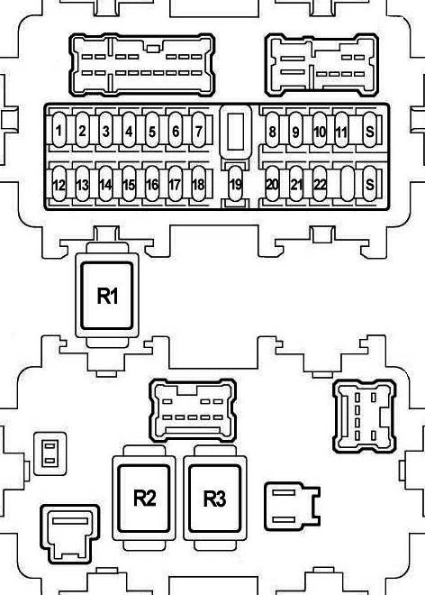
Assignment
| 1 | 10A Pedal Adjusting Control Unit, Stop Lamp Switch |
| 2 | 10A Front Blower Motor Relay, Front Air Control |
| 3 | 15A Body Control Module (BCM), Auto Anti-Dazzling Inside Mirror |
| 4 | 10A Audio, AV Switch, Display Unit, Display Control Unit, Navi Control Unit, DVD Player, Satellite Radio Tuner, Body Control Module (BCM) |
| 5 | 15A Front Power Socket 2, Rear Power Socket (2nd Row) |
| 6 | 10A Door Mirror Remote Control Switch |
| 7 | Not Used |
| 8 | 10A Door Mirror |
| 9 | 10A Driver Seat Control Unit, Diode 1 |
| 10 | 15A Rear Blower Motor |
| 11 | 15A Rear Blower Motor |
| 12 | 10A Automatic Speed Control Device (ASCD) Brake Switch, Data Link Connector, Combination Meter, Heated Seat Relay, Park Neutral Position Switch, Display Unit, Steering Angle Sensor, Display Control Unit, Navi Control Unit, Back Door Control Unit, Sliding Door Control Unit RH/LH, Sonar Control Unit, Daytime Running Lights, Hands Free Telephone |
| 13 | 10A Air Bag Diagnosis Sensor Unit, Occupant Classification System Control Unit |
| 14 | 10A Combination Meter, Park Neutral Position Switch, Auto Dimming Inside Mirror |
| 15 | Not Used |
| 16 | 10A Injectors, Body Control Module (BCM), Engine Control Module (ECM) |
| 17 | 10A Navi Control Unit, Back Door Control Unit, Sliding Door Control Unit RH/LH, Driver Seat Control Unit, Seat Memory Switch, Auto Drive Positioner Control Unit |
| 18 | 15A Subwoofer |
| 19 | 15A Transmission Control Module (TCM), A/V Switch, Display Unit, Steering Angle Sensor, Combination Meter, Front Electronic Controlled Engine Mount, Display Control Unit, Key Switch, Front Air Control |
| 20 | 10A Stop Lamp Switch |
| 21 | 15A Front Power Socket 1, Rear Power Socket (Cargo) |
| 22 | 15A Fuel Lid Opener Relay, DVD Player |
Fuse number 5, 15A, is responsible for the cigarette lighter
- R1 – Seat heating relay
- R2 – Heater relay
- R3 – Relay additional equipment
Engine compartment
In the engine compartment there are 2 main boxes with relays and fuses, and fuses on the positive terminal of the battery.

Fuse box 1

Located next to the barrel of washer fluid.

Diagram

Designation
| 32 | 20A Rear Window Defogger Relay |
| 33 | 10A Air Conditioner Relay |
| 34 | 15A IPDM E/R CPU |
| 35 | 15A Engine Control Module (ECM), ECM Relay, NATS Antenna Amplifier |
| 36 | 15A Headlamp Low (right), Diode 3 |
| 37 | 20A Rear Window Defogger Relay |
| 38 | 10A Headlamp High (left), Daytime Running Lights Control Unit |
| 39 | 30A Front Wiper Relay |
| 40 | 10A Headlamp High (right), Daytime Running Lights Relay, Diode 3 |
| 41 | 15A Tail Lamp Relay, Cornering Lamp Relay, IPDM E/R CPU |
| 42 | 10A Heater Pump Relay |
| 43 | 15A Front Fog Lamp Relay |
| 44 | 15A Throttle Control Motor Relay |
| 45 | 15A Headlamp Low (left), Daytime Running Lights |
| 46 | 15A Air Flow Sensor, Heater Oxygen Sensor |
| 47 | 10A Combination Switch (Front Wiper and Washer, Rear Wiper and Washer) |
| 48 | 10A Transmission Control Module (TCM), Revolution Sensor, Turbine Revolution Sensor, A/T PV IGN Relay |
| 49 | 10A ABS |
| 50 | 15A Fuel Pump Relay |
| Relays | |
| R1 | Engine Control Module |
| R2 | Headlamp High |
| R3 | Headlamp Low |
| R4 | Starter |
| R5 | Ignition |
| R6 | Cooling Fan (No.1) |
| R7 | Cooling Fan (No.3) |
| R8 | Cooling Fan (No.2) |
| R9 | Throttle Control Motor |
| R10 | Fuel Pump |
| R11 | Front Fog Lamp |
Fuse box 2
Located next to the battery.

Diagram

Designation
| 24 | 20A Trailer Tow Power Supply |
| 25 | 15A Horn Relay |
| 26 | 10A Generator |
| 27 | 15A Heated Seat Relay |
| 28 | 20A Front Blower Motor Relay |
| 29 | 15A Daytime Running Lights |
| 30 | 20A Front Blower Motor Relay |
| 31 | 20A Audio, BOSE Amplifier, Satellite Radio Tuner |
| F | 40A ABS |
| G | 40A Cooling Fan Relay 2 |
| H | 40A Cooling Fan Relay 1, Cooling Fan Relay 3 |
| I | 40A Circuit Breaker 1 (Slide Door Auto Closure System, Power Seat) |
| J | 50A Body Control Module (BCM) |
| K | 40A Ignition Switch |
| L | 40A ABS |
| M | 40A Circuit Breaker 2 (Adjustable Pedal System, Automatic Drive Positioner, Slide Door Auto Closure System, Power Seat) |
| Relays | |
| R1 | Horn |
| R2 | Front Blower Motor |
High power fuses
They are located on the positive terminal of the battery.

Allocation
- A – 140A Generator, Fuses D, E
- B – 80A Accessory Relay (Fuses 4, 5, 6), Rear Blower Motor Relay (Fuses 10, 11), Fuses 3, 17, 18, 19, 20, 21, 22
- C – 60A Ignition Relay (Fuses 42, 46, 47, 48, 49, 50), Fuses 33, 34, 35, 37
- D – 80A Headlamp High Relay (Fuses 38, 40), Headlamp Low Relay (Fuses 36, 45), Fuses 32, 39, 41, 43, 44
- E – 100A Fuses F, G, H, J, 24, 25, 26, 27
On our YouTube channel, we also posted a video. Watch and subscribe.