The 4th generation Mitsubishi Outlander was produced in 2022, 2023, 2024, 2025, 2026, 2027 with various engine options, including the hybrid version of the Outlander PHEV. During this time, the model received an update. In this post, you can find a description of the fuses and relays of the Mitsubishi Outlander 4 with fuse box diagrams, their locations and photo examples of execution. Let’s highlight the fuse responsible for the cigarette lighter.
The design of the units may differ from that shown and depends on the year of manufacture and the level of electrical equipment in your vehicle.
Passenger compartment
Fuse box is installed under the panel on the driver’s side behind a protective cover.
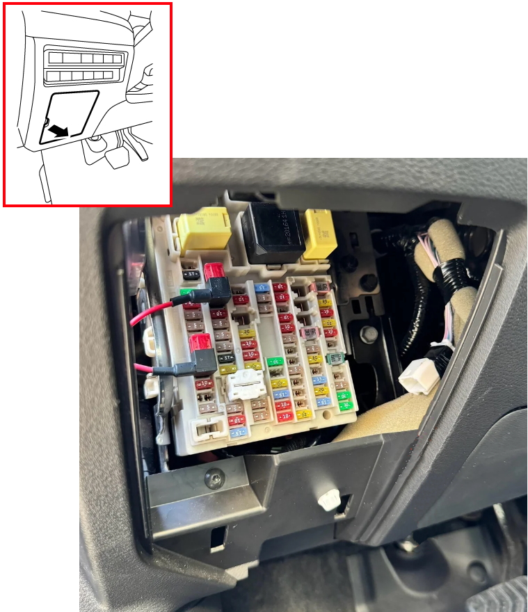
Check the description with your diagrams on the back of the cover.

Diagram

Assignment
| 1 | Rear window defroster relay |
| 2 | Outside rear view mirror (left, right) |
| 3 | – |
| 4 | Wireless charger |
| 5 | Steering wheel angle sensor |
| 6 | Instrument cluster |
| 7 | Airbag diagnostic unit and passenger detection system control unit |
| 8 | – |
| 9 | 8-channel CAN gateway, auto-dimming mirror, AVAS control unit, driving mode switch, distance sensor, front camera unit and side radar (left, right) |
| 10 | Data connector |
| 11 | Chassis control module |
| 12 | Door lock front |
| 13 | – |
| 14 | Door lock rear |
| 15 | BCM |
| 16 | 8-channel CAN gateway |
| 17 | Charging equipment communication module and TCU |
| 18 | – |
| 19 | Auxiliary connector (power outlet in rear trunk) |
| 20 | Parking brake switch |
| 21 | BCM and brake light switch |
| 22 | 4WD system all-wheel drive |
| 23 | – |
| 24 | Tailgate automatic lock and close switch unit, luggage compartment light, map light, decorative lighting (left, right), auxiliary socket (MDL, MDR, MFL, MFR), personal lighting, rear interior light, interior light (without sunroof) and sun visor (left, right) |
| 25 | AV control unit |
| 26 | Hands-free system Sensor control unit, without connection and seat position memory switch (driver, passenger) |
| 27 | USB adapter |
| 28 | BOSE AMP sound system |
| 29 | Instrument cluster |
| 30 | BCM |
| 31 | Light and rain sensor, electric sunroof and electric sunshade |
| 32 | ABS actuator/electric unit and brake light switch |
| 33 | Power steering control unit and EPS |
| 34 | Spare |
| 35 | Spare |
| 36 | Spare |
| 37 | Spare |
| 38 | Spare |
| 39 | Spare |
| 40 | 8-channel CAN gateway, ADAS 2 control unit, surround view system control unit, chassis control module, sonar control unit and spiral cable |
| 41 | Headlight (left, right) |
| 42 | Intelligent brake with power |
| 43 | Rear USB charging port |
| 44 | Selection lever |
| 45 | Passenger door mirror control module and power window master switch |
| 46 | – |
| 47 | – |
| 48 | Head-up display unit |
| 49 | Right rear power window |
| 50 | Left rear power window |
| 51 | Power window (passenger side) |
| 52 | Power window (driver side) |
| 53 | Keyless entry key unit |
| 54 | Left front seat |
| 55 | – |
| 56 | Rear wiper |
| 57 | Right front seat |
| 58 | Hazard warning lights, turn signals |
| 59 | Front power window switch (passenger side), Vehicles with one-touch driver’s door Power window; |
| 60 | Washer pump |
| 61 | Console power socket (cigarette lighter) |
| 62 | Steering wheel heating relay |
| 63 | Console power socket (cigarette lighter) |
| 64 | – |
| 65 | Third row seat heater |
| 66 | Second row seat heater (left, right) |
| 67 | First seat heater (left, right) |
| 68 | – |
| 69 | – |
| 70 | – |
| FF | – |
| GG | – |
| HH | – |
| II | – |
| J1 | Ignition relay 2 |
| J2 | Interior lighting relay |
| J3 | Ignition relay |
| J4 | Rear window defroster relay |
| J5 | Accessory relay |
| J6 | Power window relay |
| JJ | Electric rear door (trunk) |
| KK | |
| LL | Blower motor |
The front cigarette lighter is controlled by fuses numbered 61 and 63, rated at 20A.
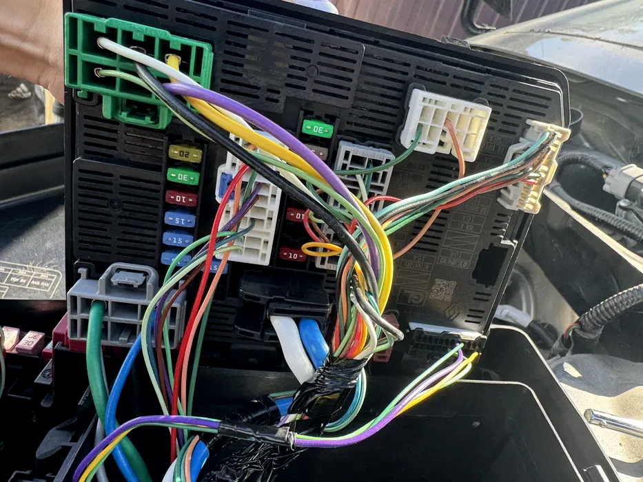
Engine compartment
Another one block with fuses and relays is installed under the hood on the left side. The battery is also connected to it via the positive terminal.

To access the first section, you need to remove the top protective cover. Inside, under the second cover, there will be a second section of the block.
Example of a diagram for the Outlander PHEV first section

Designation
| EPS | Electric power steering |
| USB | USB connector unit |
| ELEC P/LOCK | Electric door locks |
| HL WASH | Headlamp washers |
| HL WASH | Headlamp washers (additional circuit) |
| WIPER DEICER | Windshield wiper heating |
| I-BOOSTER | Electric brake booster |
| OFF LOAD2 (IGN3) | Ignition circuit relief (additional circuit) |
| EV S/B | Hybrid electrical system (Standby) |
| EV S/B | Hybrid electrical part |
| HEAD LAMP RH | Right headlamp |
| HEAD LAMP LH | Left headlamp |
| EV PUMP | Hybrid system electric cooling pump |
| OFF LOAD2 (IGN3) | Auxiliary ignition circuit |
| V2H | Vehicle-to-Home (home power from the car) |
| EV ECU | Hybrid control unit (ECU) |
| OBC | On-Board Charger |
| ELEC P/LOCK | Door locks (control) |
| CURT | Controller (probably multimedia/charging) |
| ENT HORN | Main horn |
| INST HORN | Auxiliary/ backup horn signal |
| TRAILER | Trailer electrical system (signal circuits) |
| 30A TRAILER | Trailer electrical system (power circuit) |
| HFS | Hybrid Fuse System power fuses |
Second section
Diagram

Allocation
- IGN_REV_LAMP / AC_VALVE – (REV_LAMP – reversing lights (from ignition) / AC_VALVE – air conditioner electromagnetic valve)
- IGN_AT – Automatic transmission control system (power supply to the automatic transmission ECU from the ignition switch)
- AGN_AIRBAG / ABS – Airbags and ABS unit (anti-lock braking system)
- ACTUATOR – Various engine actuators (throttle valve, turbine control valves, etc., depending on the configuration)
- IGN_ECM – Engine control unit (ECM / ECU), power is supplied when the ignition is on
- FR_WIPER – Front wipers
- IGN_WASHER_MTR – Windshield washer pump (power supply from ignition)
- BAT_ABS – Constant power supply to the ABS unit (comes directly from the battery)
- FUEL_PUMP – Fuel pump
If you know how to make the post better, write in the comments.