Mitsubishi Delica D5 was produced in 2007, 2008, 2009, 2010, 2011, 2012, 2012, 2013, 2014, 2014, 2015, 2016, 2017, 2018. After that, the model received a restyling. In this post we will present a description of fuses and relays Mitsubishi Delica d5 with fuse box diagram, their locations and photo examples of performance. Let’s highlight the cigarette lighter fuse.

Fuse and relay assignments may differ from those shown and depend on the year of manufacture and the level of electrical equipment in your vehicle.
Passenger compartment
In the passenger compartment, the fuse and relay box is located in the instrument panel on the passenger side, behind the glove compartment. The glove box itself must be removed for access.

Photo – example of location

Check the assignment with your diagrams on the back of the protective cover.
Image of the box cover

Diagram

Protected components
| 1 | 30A Heater / heater |
| 2 | 15A Stop lights |
| 3 | 10A Rear fog lamp |
| 4 | 30A Glass windshield wiper |
| 5 | Reserve |
| 6 | 10A Chain of additional equipment |
| 7 | 20A Door locks |
| 8 | 15A Audio system |
| 9 | 7.5A A chain of additional equipment |
| 10 | 15A Interior lamps |
| 11 | 15A Hazard warning lights |
| 12 | 15A Glass Tailgate Window Cleaner |
| 13 | 7,5А Control and measuring devices |
| 14 | Reserve |
| 15 | 15A Cigarette lighter (front power outlet) |
| 16 | 10A Ignition lock |
| 17 | 20A Electric sunroof |
| 18 | Reserve |
| 19 | 10A Exterior mirrors |
| 20 | 10A All-wheel drive system |
| 21 | 7.5A Reversing lights |
| 22 | Reserve |
| 23 | 15A Additional power socket |
| 24 | 30A Electric windows |
| 25 | 30A Heated tailgate glass |
| 26 | 7,5А Heated outside rear-view mirrors |
| 27 | 15A Power supply |
| 28 | 20 / 25A Electric seat |
| 29 | 30A Seat heating |
The fuse number 15 is responsible for the cigarette lighter, and the fuse is 23 for 15A for the socket.
Relay assignment
- Door lock relay
- Heater relay
- Seat heating relay
- Tailgate glass heater relay
Engine compartment
Main box
Installed on the left side of the engine compartment.

Diagram
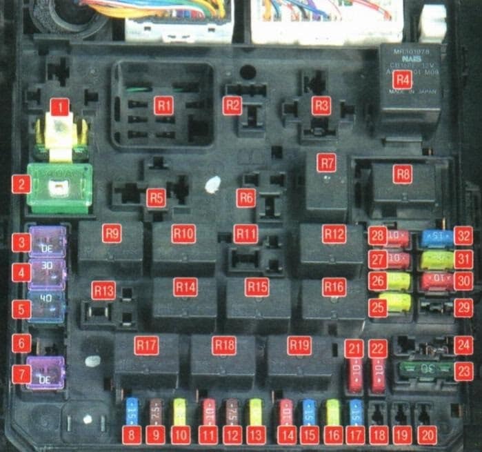
Designation
| 1 | 30A I / O device |
| 2 | 40A Cooling fan motor |
| 3 | 30A Condenser fan motor |
| 4 | 30A ABS |
| 5 | 40A ABS |
| 6 | Reserve |
| 7 | 30A Starter |
| 8 | 15A Front fog lights |
| 9 | 7.5 Engine management |
| 10 | 20A AKP |
| 11 | 10A Sound signal |
| 12 | 7.5A Generator |
| 13 | 20A Headlight washer |
| 14 | 10A Air conditioner |
| 15 | 15A Throttle valve |
| 16 | 20A Anti-theft alarm sound |
| 17 | 15A Heated wiper blades |
| 18 | Reserve |
| 19 | 30A Electric tailgate |
| 20 | 10A Outdoor lighting system during the day |
| 21 | 10A High beam headlamp (left) |
| 22 | 10A High beam headlamp (right) |
| 23 | 30A Audio amplifier |
| 24 | 30A Diesel engine electrical equipment |
| 25 | 20A Left low beam headlamp (with discharge lamps) |
| 26 | 20A Right-hand dipped beam headlamp (with discharge lamps) |
| 27 | 10A Left low beam headlamp (with halogen bulbs) |
| 28 | 10A Right-hand dipped beam headlamp (with halogen bulbs) |
| 29 | 10A Engine power supply circuit |
| 30 | 10A Ignition coil |
| 31 | 20A Engine power supply circuit |
| 32 | 15A Fuel pump |
Relay decoding
| R1 | Glow plug relay (for diesel engines) |
| R2 | Radiator fan relay |
| R3 | Heater relay |
| R4 | Engine control relay |
| R5 | Stability Relay |
| R6 | A / C Radiator Fan Relay |
| R7 | Engine control relay |
| R8 | Headlamp low beam relay |
| R9 | Engine control relay |
| R10 | Wiper blade heater relay |
| R11 | Daytime outdoor lighting relay |
| R12 | Engine control relay |
| R13 | Anti-theft alarm relay |
| R14 | Automatic transmission relay |
| R15 | Headlight washer relay |
| R16 | Headlamp high beam relay |
| R17 | Front fog lamp relay |
| R18 | Horn relay |
| R19 | Air conditioner relay |
Relay box

Located next to the main one.
Diagram

Assignment
- R1 Relay for low speed fan of the engine cooling system
- R2 Air conditioner fan relay
- R3 Relay for high speed fan of the engine cooling system
Battery box
The positive terminal of the battery contains a high-power fuse box in the form of fusible links.

Is there anything to add to the material? Write in the comments.