Mercedes ML W166 represents the third generation of the Mercedes-Benz M-Class SUV which was produced in 2012, 2013, 2014, 2015, 2016, 2017, 2018, 2019, 2020 and delivered worldwide. During this time, the model has been restyled. This information will also be useful to the owners of the Mercedes GL X166 and Mercedes GLS X166, because these cars have similar electrical circuits. In it you can find a description of the fuses and relays Mercedes 166 with box diagrams, photo examples of their performance and locations. Note the fuse responsible for the cigarette lighter.

The purpose of the fuses and relays in the boxes may differ from the one shown and depends on the year of manufacture, the level of equipment and the region of delivery of your car.
Contents
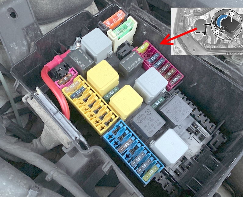
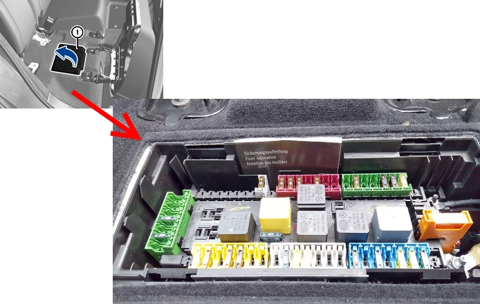
Engine compartment
Location
Layout

Assignment
- F32/3 – Power fuse box
- F58 – Fuse and relay box
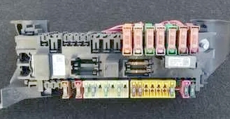
Fuse and relay box
Photo – example
Diagram
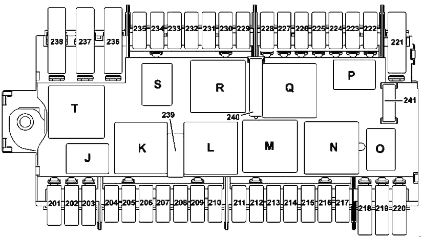
Designation
| 201 | Reserve |
| 202 | 20A Auxiliary heater heater |
| 203 | 5A Alarm Siren |
| 204 | 25A Electronic motion stabilization control unit |
| 205 | 15A Left horn |
| Right horn | |
| 206 | Reserve |
| 207 | Reserve |
| 208 | Reserve |
| 209 | Reserve |
| 210 | Reserve |
| 211 | Reserve |
| 212 | Reserve |
| 213 | 7.5A Valid for engines 642, 651: |
| CDI control unit | |
| Valid for engine 157, 276, 278: | |
| ME control unit | |
| 214 | 15A Valid for engine 157, 276, 278: |
| ME control unit | |
| Valid for vehicles with engine 651: | |
| CDI control unit | |
| BlueTEC: | |
| Nox sensor control unit | |
| 215 | 15A Valid for vehicles with engine 157, 276, 278: |
| Electrical plug connection engine/engine compartment (pin 7) | |
| Valid for vehicles with engine 642: | |
| Electrical plug-in connection for motor/engine compartment (pin 7) via terminal 87 D3 cable gland | |
| Radiator shutter actuator | |
| Valid for vehicles with engine 651: | |
| Electrical plug connection engine/engine compartment (pin 7) | |
| Radiator shutter actuator | |
| 216 | 15A Valid for engine 157, 276, 278: |
| Cable termination, terminal 87D2 | |
| Valid for vehicles with engine 642: | |
| CDI control unit | |
| Electrical plug connection engine/engine compartment (pin 6) | |
| Adjustable left engine mount | |
| Adjustable right engine mount | |
| Valid for vehicles with engine 651: | |
| Fan motor | |
| CDI control unit | |
| Electrical plug connection engine/engine compartment (pin 6) | |
| Adjustable engine mount, left (Y123) Adjustable engine mount, right | |
| 217 | 20A Valid for engine 157, 276, 278: |
| Electrical plug connection engine/engine compartment (pin 5) | |
| Valid for engines 642, 651: | |
| CDI control unit | |
| Electrical plug connection engine/engine compartment (pin 5) | |
| 218 | Reserve |
| 219 | 10A Valid for engine 278, 157: Charge air cooler circulation pump |
| 220 | Reserve |
| 222 | Reserve |
| 223 | Reserve |
| 224 | Reserve |
| 225 | Reserve |
| 226 | Reserve |
| 227 | Reserve |
| 228 | Reserve |
| 229 | 7.5A Front left headlight |
| 230 | 5A Control unit for electronic stability control |
| 231 | 7.5A Front right headlight |
| 232 | 15A Fully integrated gearbox control unit |
| Vehicles without “ECO Start-Stop” function: Additional transmission oil pump control unit | |
| 233 | 15A Headlight control unit |
| 234 | 5A Electrical control module DISTRONIC |
| 235 | 20A Heated wiper blades |
| 236 | Reserve |
| 237 | 15A KP 722.9: Servo drive module for automatic transmission for DIRECT SELECT system |
| 238 | 40A Compressor AIRMATIC |
| 239 | 30A Wiper motor |
| 240а | 30A Vehicles without “ECO Start-Stop” function: Starter |
| 240b | 30A Vehicles with “ECO Start-Stop” function: Engine compartment power fuse box |
| 241 | Reserve |
| Relay | |
| J | Horn relay |
| K | Wiper Mode Relay 1/2 |
| L | Wiper relay on/off |
| M | Starter terminal 50 relay |
| N | Relay el. circuit terminals 87M |
| O | Turbocharger relay |
| P | Reserve relay |
| Q | Terminal 15 relay (no support) |
| R | Relay terminal 15 |
| S | Relay for heated wiper blades |
| T | AIRMATIC relay |
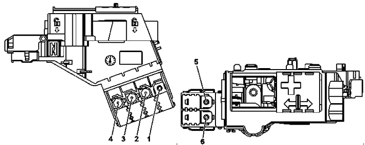
Power fuse box
Photo

Diagram
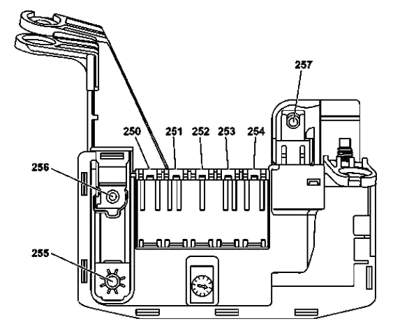
Allocation
| 250 | 40A SAM control unit |
| 251 | 40A SAM control unit |
| 252 | 40A SAM control unit |
| 253 | 30A Front left door control unit |
| 254 | 30A Rear left door control unit |
| 255 | 200A Battery compartment power fuse box |
| 256 | 150A Rear fuse box |
| 257 | 150A Diesel engine: Additional electric heater |
It is possible to install some elements of the relay outside these blocks, for example, a relay for heating hoses to washer nozzles.
Passenger compartment
Location
Layout

Appointment
- F3 / 2, F3 / 3 – Fuse box in the instrument panel
- F4 – Main fuse and relay box in the rear
- F32/4 – Power fuse box
- F33 – Battery compartment fuse box
- F270 – Buffer battery fuse
Fuse and relay box
The main box with fuses and relays in the passenger compartment is located under the rear seat and is closed with a protective cover.
Diagram

Decoding
| 100 | 5A Audio module |
| COMAND control module | |
| Electrical plug connection for external navigation | |
| 101 | 20A Trailer detection control unit |
| 102 | 7.5A Driver’s seat control unit |
| 103 | 7.5A Front passenger seat control unit |
| 104 | 5A Antenna Amplifier / Mobile Phone Compensator |
| Bluetooth® module | |
| 105 | 5A Holder for navigation module |
| 106 | 5A Tailgate control unit |
| 107 | 10A Release module, 2nd row of seats, left |
| Release module, 2nd row of seats, right | |
| 108 | Reserve |
| 109 | Reserve |
| 110 | 5A AdBlue® control unit |
| 111 | 15A Trailer socket |
| 112 | 5A Fuel pump control unit |
| 113 | 5A Electric parking brake control unit |
| 114 | 5A Switch for exterior lighting |
| 115 | 5A Trailer detection control unit |
| 116 | 5A Termination of terminal 87 of the radar control unit |
| COLLISION PREVENTION ASSIST control module | |
| 117 | 5A Night vision control unit |
| 118 | Reserve |
| 119 | 5A Transfer case control unit |
| 120 | 5A Fuel quality sensor |
| Digital tachograph control unit | |
| 121 | Reserve |
| 122 | Reserve |
| 123 | Reserve |
| 124 | 30A Electrical plug connection for the Elektric Brake Control function |
| 125 | Reserve |
| 126 | 15A Trailer recognition control unit |
| 127 | 30A Driver seat control unit |
| 128 | 20A Trailer recognition control unit |
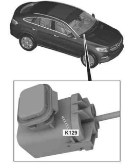
| 129 | 30A Front passenger seat control unit |
| 130 | 20A Trailer recognition control unit |
| 131 | Reserve |
| 132 | 25A Fuel pump control unit |
| 133 | 5A Radio remote control receiver for auxiliary heater |
| 134 | 5A Seat occupied recognition pressure sensor |
| Occupancy recognition and AKSE, front passenger seat | |
| 135 | 5A Glove box light |
| 136 | 7.5A Control unit for passenger restraint system (Supplemental Restraint System) |
| 137 | 5A Electric fuse preparation for installation of the Electronic Toll Collection system |
| Electronic equipment rear view camera | |
| Electrical plug connection for external navigation | |
| 138 | 15A Active roll stabilization control unit |
| 139 | Reserve |
| 140 | 7.5A AdBlue® control unit |
| 141 | 15A AdBlue® control unit |
| 142 | 20A AdBlue® control unit |
| 143 | Reserve |
| 144 | Reserve |
| 145 | 7.5A Cup holder |
| 146 | 30A Rear window notch filter |
| 147 | 30A Audio module |
| COMAND control module | |
| 148 | 15A Cigarette lighter heating element |
| Detachable cup holder connection | |
| 149 | 5A Socket 115 V |
| 150 | 20A Socket in trunk |
| 151 | 20A Socket, 2nd seat row, left |
| Socket in the 2nd row of seats on the right | |
| 152 | 30A Rear compartment systems control unit |
| 153 | 25A AC/DC converter control unit |
| 154 | 40A Tailgate control unit |
| 155 | Reserve |
| 156 | Reserve |
| 157 | 15A Tailgate wiper motor |
| Relay | |
| А | Relay socket terminals 15R2 |
| B | Heated rear window relay |
| C | Backup relay |
| D | AdBlue® relay |
| E | Relay terminal 15 |
| F | Rear window wiper relay |
| G | Relay terminal 15R1 |
| H | Backup relay |
| I | Backup relay |
Fuses 148 – 151 are responsible for the cigarette lighter.
Fuse box in the panel
A fuse box is installed at the right end of the instrument panel, behind a protective cover.

Diagram

Assignment
- 10 7.5A Electronic ignition lock control unit
- 11 10A Steering column electronic module control unit
- 12 5A Instrument cluster
- 13 15A Auxiliary fan electronic control
- 14 5A Diagnostic connector
- 15 5A Upper control box
- 16 Reserve
- 17 Reserve
- 18 Reserve
- 19 15A Climate Control Panel
- 20 5A Steering column electronic module control unit
- 21 7.5A Audio/ COMAND display
- 22 Reserve
Battery compartment fuse box
In a niche next to the battery, another fuse box is installed.
Diagram

Designation
| 30 | 40A Speaker amplifier control unit |
| 30A Woofer Amplifier | |
| 31 | 40A Engine compartment fuse and relay module |
| 32 | 40A Fan regulator |
| 33 | 40A Front left reversible seat belt pretensioner |
| 34 | 40A Rear fuse box |
| 35 | 40A Front right seat belt reversible pretensioner |
| 36 | 40A Fuse box, terminal 30, front panel |
| 37 | 40A Test lead |
| 38 | Reserve |
| 39 | Reserve |
| 40 | 25A Electronic rear air conditioning fan control |
| 41 | Reserve |
| 42 | Reserve |
| 43 | Reserve |
| 44 | Reserve |
| 45 | 5A Digital tachograph control unit |
| 46 | Reserve |
| 47 | 10A Speaker amplifier control unit |
| 48 | 30A Rear compartment systems control unit |
| 49 | 5A EDW/Tow protection/Interior monitor control unit |
| 50 | 5A Emergency call system control unit |
| 51 | 5A Antenna amplifier FM 1, AM, ZV and KEYLESS-GO |
| 52 | 30A Front right door control unit |
| 53 | 15A Ceiling control box |
| 54 | Test lead |
| 55 | 30A Rear compartment systems control unit |
| 56 | 15A KeyLess-Go control unit |
| 57 | 30A Rear right door control unit |
| 58 | 30A Transfer box control unit |
| 59 | 7.5A Control unit for passenger restraint system (Supplemental Restraint System) |
| 60 | 7.5A Ceiling control box |
| 61 | Reserve |
| 62 | 15A AIRMATIC control unit |
| 63 | 20A Panoramic sliding sunroof control module |
| Sliding sunroof control module | |
| 64 | 30A Air pump for multi-contour seat |
| 65 | 30A Fuse box, terminal 30g, front panel |
| 66 | Reserve |
| 67 | 30A Electric parking brake control unit |
| 68 | 30A Electric parking brake control unit |
| MF1 | 5A Pin 1: Audio module / COMAND system control panel |
| Contact 2: | |
| Bottom Control Panel | |
| Off-road driving mode control panel | |
| Pin 3: Parking assistance control unit | |
| Pin 4: Control unit for electronic stability control | |
| Pin 5: SAM control unit | |
| Pin 6: Speaker amplifier control unit | |
| MF2 | 5A Pin 1: HBF control unit |
| Pin 2: Tire pressure monitoring control unit | |
| Contact 3: | |
| Digital audio broadcasting control unit | |
| Satellite Digital Audio Radio (SDAR) control unit | |
| Pin 4: Multi-function camera | |
| Pin 5: Multimedia interface control unit | |
| Pin 6: | |
| Rear View Camera | |
| 360° camera control box | |
| MF3 | 5A Pin 1: Rear left display |
| Pin 2: Rear right display | |
| Contact 3: | |
| TV tuner (analog/digital) | |
| Digital TV tuner | |
| Pin 4: DVD player | |
| Pin 5: Control unit for video and radar sensors | |
| Contact 6: Reserve | |
| MF4 | Contact 1: Reserve |
| Contact 2: Reserve | |
| Contact 3: Reserve | |
| Contact 4: Reserve | |
| Contact 5: Reserve | |
| Contact 6: Reserve |
Power fuse box
This high power fuse box is also located near the battery.

Diagram
Allocation
- 40A Control unit for electronic stability control
- Reserve
- 30A Vehicles with ECO Start-Stop function: Engine compartment fuse and relay module
- Reserve
- 150A Engine compartment fuse and relay module
- 125A Fan motor
- 300/400A Power fuse box in passenger compartment
- 100A Electric power steering control unit
Check out our YouTube video for more on this topic! Don’t forget to subscribe.
Found a mistake or have something to add – write in the comments.
Most of 2014 GL350 fuses have suffix “s” added to ampers, for example 15s rather than 15, and MB requires that the same type of fuse for replacement. What does ‘s’ suffix indicate?
Slow Blow fuses are marked with an S. They take a little longer to blow, a sustained overamp condition, not just a blip.
Can’t find anything related to my sound system failure to function or turn on. All fuses are well, unless there are fuses on the sound system itself that has to relay power from the fuses related to activate it. Assist wherever this may relate?
Which relay controls the fuel pump
Control module
where would the blind spot assist and lane assist fuse or relay be? thanks
Did you ever figure the answer out to this?
hello wehre are the fuse for interior light for w166b becuase i dont see in diagram
which relay controls fuel pump
no power to the turbo actuator and fuse 15a bi number 215 brocken need help pls
which fuse for turbo actuator?and 2 MAF Sensor not working in sem time
Hi
Fuse 19 is for climate control where’s the relay?
Are there fuses for the daytime running lights? Can’t find them on any list. If so, where are they? Thanks a million!
Hi, are there any fuses for the w166 (2014 ML350 Bluetec) wheel speed sensors and if so where are they located please.
Thank you
Robert
PS Love the effort you’ve put in to producing and sharing this information, Big thanks
Thank u
Which fuse box the rear SAM is attached to? Thank you!
Fusible pour réglage volant où se trouve?
Hi, I can’t find daylight fuse, my mercedes left day light isn’t working I change the light but still not working, I bought from amazon I am not sure if the light or fuse is gone.
Any help much appreciated