Mazda 626 ge, 4th generation of the Mazda 626 model, produced in 1991, 1992, 1993, 1994, 1995, 1996. And shipped all over the world. Also known as Mazda Cronos. In this article you will find a description of fuses and relays Mazda 626 ge with box diagrams, their locations and photo examples of execution. Highlight the cigarette lighter fuse.

The locations of the boxes and individual elements may differ from the one shown and depend on the region of delivery (America, Europe, Asia, Japan (Mazda Kronos)), year of manufacture and equipment level.
Contents
Passenger compartment fuse box
It is located under the dashboard, on the stand behind the protective cover, near the driver’s foot.

Legend from the box cover

Diagram

Assignment
- STOP – 20A brake lights, horn, cruise control
- ROOM-15A interior lighting, trunk lighting, warning signal system
- DOOR LOCK – 30A door lock drive system (central locking)
- RADIO – 15A audio system, cigarette lighter , outside mirrors
- SUN ROOF – 15A люк
- TURN – 15A direction indicators
- POWER SEAT – 30A electric seat
- METER – 15A instrument cluster, reverse
- HAZARD – 15A alarm
- ENGINE – 15A engine management system
- POWER WINDOW – 30A power windows
- HEAD CLEANER – 20A headlight cleaner
- WIPER – 20A wipers and washers
- REAR WIPER – 20A rear window wiper
- SPARE – 15A reserve, spare fuse
The fuse number 4, 15A, is responsible for the cigarette lighter.
Engine compartment fuse box
Several fuse and relay boxes can be installed in the engine compartment:
- Main unit
- Additional
- Relay

Main box
Located on the left side of the engine compartment, next to the battery. The actual assignment will be on your protective cover.
Diagram
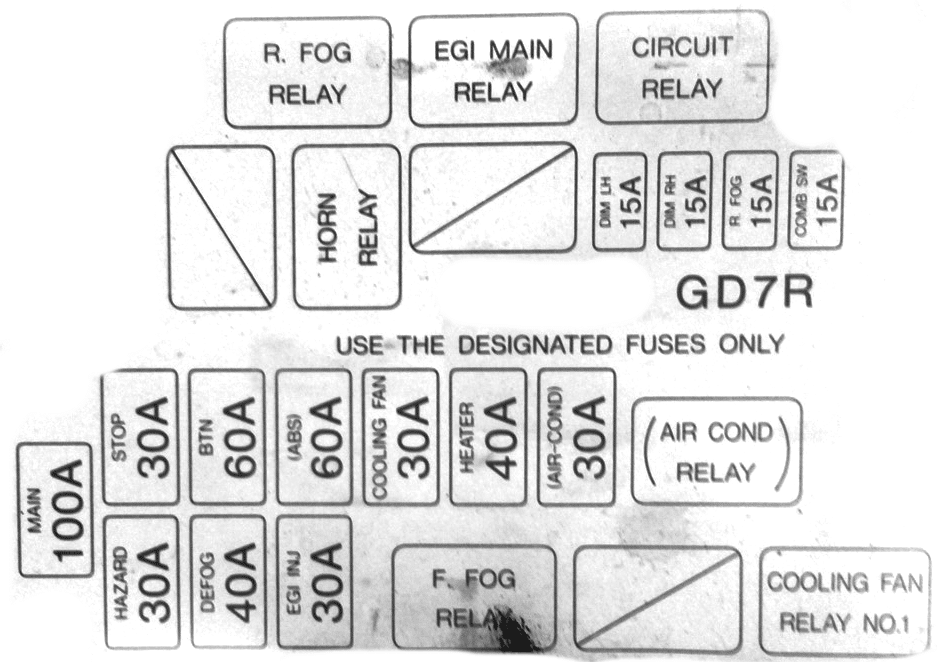
Appointment
- MAIN – 100A main fuse
- HAZARD – 30A alarm
- DEFOG – 40A rear window heating
- EJI INJ – 30A fuel injection system
- F.FOG RELAY – front fog lamp relay
- COLING FAG RELAY NO1 – cooling fan relay
- STOP – 30A brake lights
- BTN – 60A door locks, power seats
- ABS – 60A Anti Lock Brake System (ABS)
- COLING FAG – 30A cooling fan
- HEATER – 40A heater, air conditioner
- AIR COND – 30A air conditioner
- AIR COND RELAY – air conditioner relay
- HORN RELAY – horn relay
- DIM LH – 15A low beam left headlight
- DIM RH – 15A low beam right headlight
- R.FOG – 15A rear fog lights
- COMB SW – 15A for steering switches and wipers
- R.FOG RELAY – rear fog lamp relay
- EGI MAIN RELAY – engine control relay
- CIRCUIT RELAY – fuel pump relay
Additional box
Diagram

Designation
- TAIL LH – 15A Dimensions left
- TAIL RH – 15A Dimensions right
- MAIN LH – 15A Headlight, left
- MAIN RH – 15A Headlight, right
- HORN – 15A Signal
- FOG – 20A Fog lights
Relay
Depending on the region of delivery, individual relays are located both near the main unit and on the right side of the engine compartment.

A cooling fan relay, a heating relay, a fog lamp relay, etc. can be installed here.
This concludes the article. And if you have something to add to it, we will be glad to have your comments.
thank you very much
good morning sir