The updated Infiniti QX80 was produced in 2017, 2018, 2019, 2020, 2021, 2022, 2023, and 2024. In this publication, we will provide a description of the fuses and relays for the facelifted Infiniti QX80, including fuse box diagrams, their locations, and photographs. We will highlight the fuse responsible for the cigarette lighter.

Purpose of fuses and relays may differ from that described here and depends on the year of manufacture and the level of electrical equipment in your vehicle.
Contents
Passenger compartment
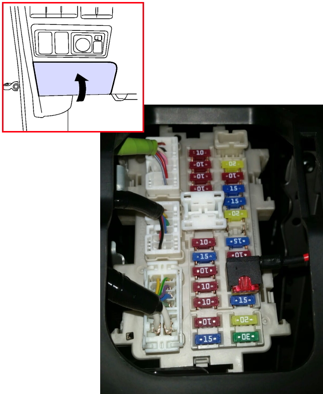
In the car’s interior, the fuse box is located under the dashboard, on the driver’s side, behind a protective cover.
Diagram
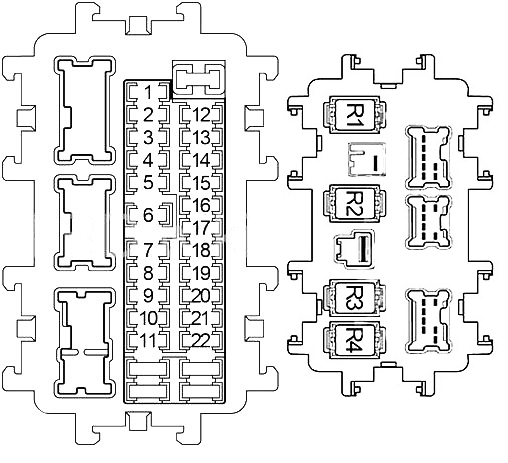
Assignment
| 1 | 10A Combination Switch |
| 2 | 10A Air Bag Diagnosis Sensor Unit, Occupant Classification System Control Unit |
| 3 | 10A Intelligent Cruise Control (ICC) Brake Switch, Automatic Speed Control Device (ASCD) Brake Switch, Stop Lamp Switch, Headlamp Aiming Motor LH/RH, Data Link Connector, Steering Angle Sensor, Combination Meter, Heated Steering Wheel Switch, Low Tire, Pressure Warning Control Unit, Power Steering Control Unit, CAN Gateway, Triple Switch (APS Switch), Adaptive Front Lighting System (AFS) Control Unit, AC 120V Outlet Main Switch, Climate Controlled Seat Relay |
| 4 | 10A Rear A/C Control, Around View Monitor Control Unit, A/C Auto Amplifier, Ionizer, AV Control Unit, Rear A/C Relay, Exhaust Gas / Outside Door Detecting Sensor, Automatic Back Door Control Module, Auto Anti-Dazzling Inside Mirror, Sonar Control Unit, Telematics Control Module |
| 5 | 15A BOSE Amplifier |
| 6 | 10A Data Link Connector, Clock, Second Seat Power Unlock Switch LH/RH, Intelligent Key Warning Buzzer, Pre-crash Seat Belt Control Unit, Lights Rain Sensor, Auto Anti-dazzling Inside Mirror, Combination Meter |
| 7 | 10A Stop Lamp Switch, Body Control Module (BCM), Intelligent Cruise Control (ICC) Brake Hold Relay, Electric Brake |
| 8 | 15A BOSE Amplifier |
| 9 | 10A Around View Monitor Control Unit, A/C Auto Amplifier, Automatic Back Door Control Module, Reclining Switch LH/RH, Fold Down Switch LH/RH, Automatic Back Door Warning Buzzer |
| 10 | 10A Push-Button Ignition Switch, Seat memory Switch, Body Control Module (BCM) |
| 11 | 10A Combination Meter, CAN Gateway |
| 12 | 20A Accessory Relay №2 |
| 13 | 10A 4WD Switch, Snow Mode / Tow Mode / VDC off Switch Assembly |
| 14 | 15A Second Heated Seat Switch LH/RH |
| 15 | 15A Front Heated Seat Switch LH/RH |
| 16 | 20A Rear Blower Relay |
| 17 | – |
| 18 | 20A Console Power Socket |
| 19 | 10A Door Mirror Remote Control Switch (2010-2013), Sonar Control Unit (2010-2013), Around View Monitor Control Unit, A/C Auto Amplifier, Multifunction Switch, AV Control Unit, Front Display Unit, Video Distributor, Power Window Main Switch (2014-2017), BOSE Amplifier (2014-2017), Telematics Control Module (TCU (2014-2017)), Telematics Switch (2014-2017) |
| 20 | 20A Front Power Socket, Luggage Room Power Socket, Accessory Relay №2 |
| 21 | 15A Front Blower Motor |
| 22 | 15A Front Blower Motor |
| Relay | |
| R1 | Ignition |
| R2 | Ignition №2 |
| R3 | Accessory |
| R4 | Blower |
Fuse number 18 or 20 are responsible for the cigarette lighter.
Engine compartment
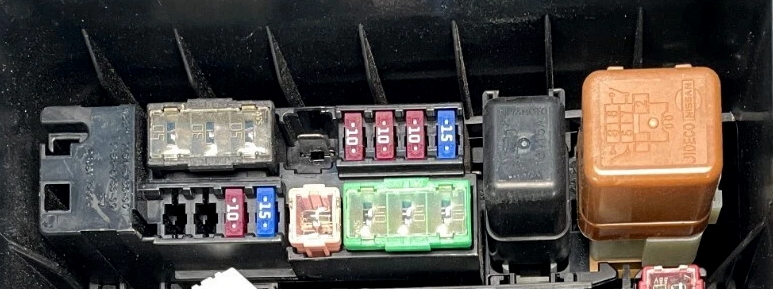
Under the hood, in the engine compartment of the car, on the left side, next to the battery, there are 4 blocks with fuses and relays.

Check the actual description with yours on the back side of the protective cover.

Fuse Box 1

Diagram

Designation
| 41 | 15A Rear Window Defogger Relay |
| 42 | 15A Rear Window Defogger Relay |
| 43 | 20A Engine Control Module (ECM), NATS Antenna Amplifier, ECM Relay (Mass Air Flow Sensor, Evap Canister Purge Volume Control Solenoid Valve, Variable Valve Event and Lift (VVEL) Control Module, Intake Valve Timing Control Solenoid Valve, Air Fuel Ratio (A/F) Sensor, Heated Oxygen Sensor, Fuel Return Valve, EVAP Canister Vent Control Valve |
| 44 | 10A Steering Lock Relay |
| 45 | 30A Front Wiper Relay |
| 46 | 10A Trailer Tail Lamp Relay, Rear Combination Lamp LH, Tail Lamp RH/LH, License Plate Lamp |
| 47 | 10A Glove Box Lamp, Climate Controlled Seat Switch, Rear A/C Control, Around View Monitor Control Unit, Heated Steering Wheel Switch, 4WD Switch Assembly, A/T Shift Selector, Multifunction Switch, Front Heated Seat Switch< Second Heated Seat Switch LH/RH, Clock, Second Seat Power Unlock Switch LH/RH, Electric Brake, AC 120V Outlet Main Switch, Console Power Socket (Cup Holder), Snow Mode / Tow Mode / Vdc Off Switch Assembly, Headlamp Aiming Switch, Door Mirror Remote Control Switch, Combination Switch (Spiral Cable), Hazard Switch, Trip Reset and Illumination Control Switch, Trip Computer Switch, Automatic Back Door Main Switch, Triple Switch, Twin Switch, Rear Combination Lamp RH, Mood Lamp Front Door Grip, Mood Lamp Rear Door Grip, Map Lamp, Telematics Sswitch |
| 48 | – |
| 49 | 10A A/C Relay |
| 50 | 15A Front Fog Lamp |
| 51 | 10A Right Headlamp (High Beam) |
| 52 | 10A Left Headlamp (High Beam) |
| 53 | 15A Left Headlamp (Low Beam) |
| 54 | 15A Right Headlamp (Low Beam) |
| 55 | 10A Back-Up Lamp Relay, Trailer Power Relay, Transmission Control Module (TCM) |
| 56 | 10A Transfer Control Unit |
| 57 | 10A ABS, Stop Lamp Relay, Yaw Rate / Side / Decel G Sensor |
| 58 | – |
| 59 | – |
| 60 | 15A Injector Relay |
| 61 | 15A Ignition Coils, Condenser |
| 62 | 10A Engine Control Module (ECM) |
| 63 | – |
| 64 | 20A Throttle Control Motor Relay |
| Relay | |
| R1 | Rear Window Defogger |
| R2 | Ignition №3 |
| R3 | Ignition №2 |
| R4 | Ignition |
Fuse Box 2
Diagram
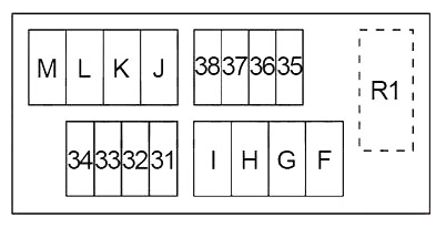
Allocation
| 31 | 15A Horn Relay |
| 32 | 10A Alternator |
| 33 | 10A Accelerator Pedal Actuator |
| 34 | 10A Transfer Control Unit |
| 35 | 15A AV Control Unit, Front Display Unit, Video Distributor, Headrest Display Unit LH/RH, Telematics Control Module |
| 36 | 10A Vehicle Security Horn Relay |
| 37 | 10A IPDM (Ignition Relay №2 (Air Levelizer Control Module), Ignition Relay №3 (Warning Buzzer, Twin Switch (Warning Systems Switch), Intelligent Cruise Control (ICC) Brake Hold Relay, Intelligent Cruise Control (ICC) Sensor, Accelerator Pedal Actuator, Advanced Driver Assistance Systems (ADAS) Control Unit, Side Radar LH/RH, Lane Camera Unit) |
| 38 | 10A Transmission Control Module (TCM) |
| F | 40A Electric Brake, Fuse: “T”, “V”, “79”, “84”, “85”, “86” |
| G | 40A Ignition Relay №1 (Fuse: “1”, “2”, “3”, “4”, “16”), Fuse: “12”, “81”, “82”, “83”, “U” |
| H | 40A IPDM |
| I | 30A Air Compressor Relay |
| J | 30A Transfer Control Unit |
| K | 50A Body Control Module (BCM), Circuit Breaker (Automatic Drive Positioner Control Unit, Driver Seat Control Unit, Lumbar Support Switch) |
| L | 30A ABS |
| M | 50A ABS |
| Relay | |
| R1 | Horn |
Additional fuses

Diagram
Appointment
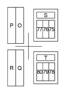
| P | 50A Ignition Relay (Fuse: “71”, “72”, “73”, “74”) |
| O | 50A Variable Valve Event and Lift (VVEL) Actuator Motor Relay |
| R | 50A Fuse: “T”, “79” |
| Q | 50A Fuse: “S”, “75”, “76”, “77” |
| 50A Fuse: “S”, “75”, “76”, “77”, “87”, “88”, “89”, “90” | |
| 75 | 15A Wiper Deicer Relay |
| 76 | 10A Heated Steering Wheel Relay |
| 77 | 30A Pre-Crash Seat Belt Control Unit |
| S | 30A Second Row Seats (Power Unlock Relay LH/RH, Up Relay 2 LH/RH, Down Relay 2 LH/RH) |
| 78 | – |
| 79 | 30A Inverter Unit |
| 80 | 10A Wiper Deicer Relay, Door Mirror |
| T | 30A Automatic Back Door Control Module |
Relay box 1
This relay box is located behind the main fuse and relay box.
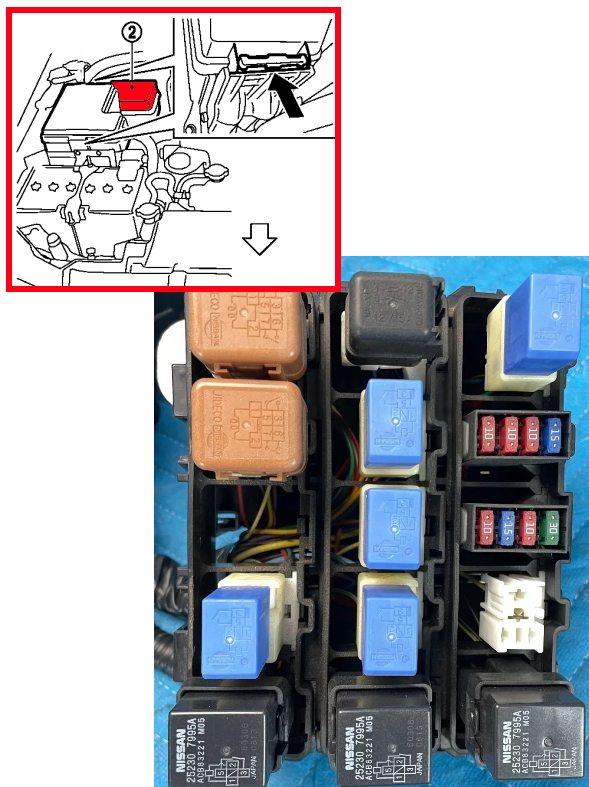
Diagram from the covery

Diagram
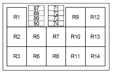
Decoding
| 71 | 30A Engine Control Module (ECM) |
| 72 | 10A Electrically Controlled Cooling Fan Coupling |
| 73 | 15A Fuel Pump Control Module |
| 74 | 10A ABS |
| 87 | 15A Injector Relay |
| 88 | 10A Daytime Running Light Relay |
| 89 | 10A Daytime Running Light Relay |
| 90 | 10A Daytime Running Light Relay |
| Relay | |
| R1 | Remote Engine Start |
| R2 | – |
| R3 | Vehicle Security Horn |
| Daytime Running Light | |
| R4 | – |
| R5 | – |
| R6 | Back-Up Lamp |
| R7 | Heated Steering Wheel |
| R8 | Intelligent Cruise Control (ICC) Brake Hold |
| R9 | Wiper Deicer |
| R10 | Rear A/C |
| R11 | Stop Lamp |
| R12 | Air Compressor |
| R13 | Ignition |
| R14 | Variable Valve Event and Lift (VVEL) Actuator Motor |
Relay box 2
This relay box is installed on the other side of the engine compartment.
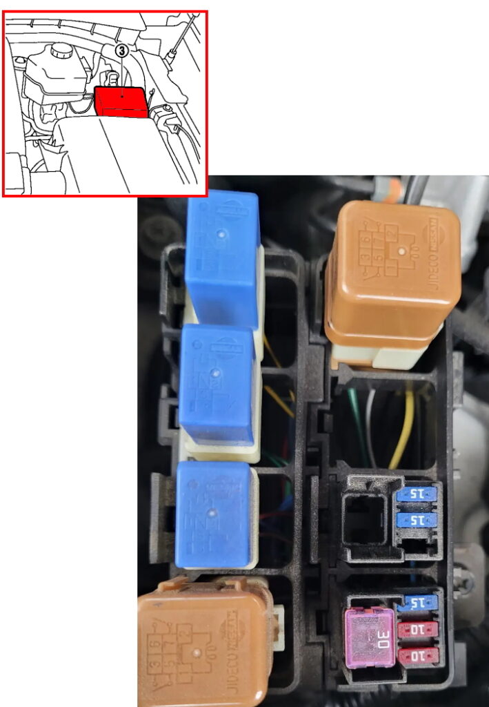
Example of diagram from the covery
Diagram
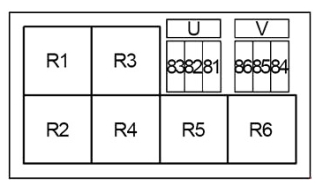
Description
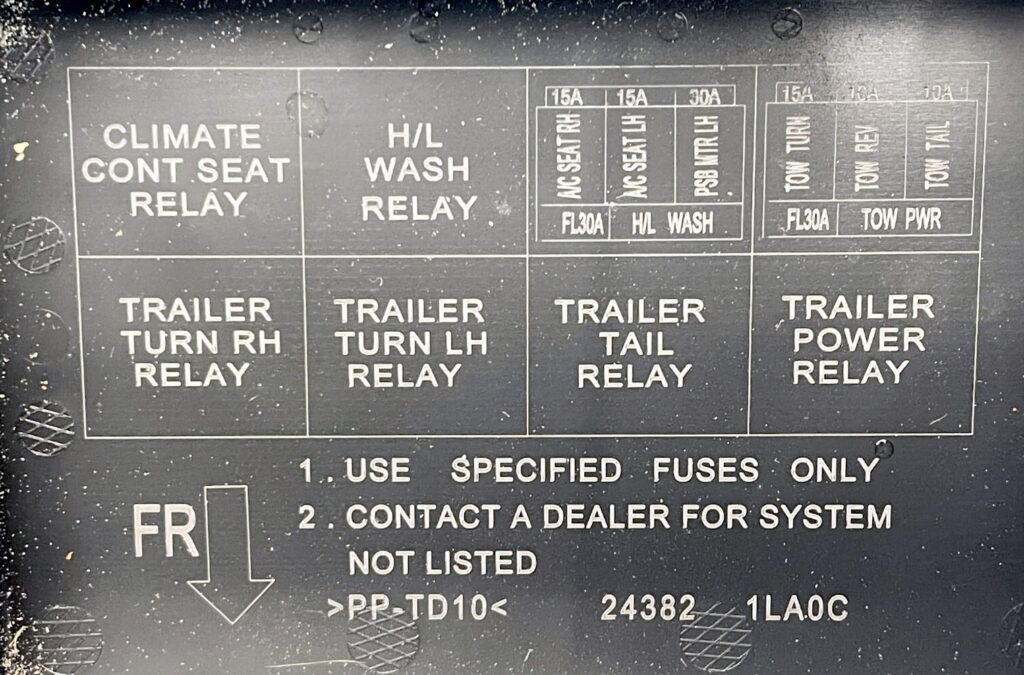
| 81 | 30A Pre-Crash Seat Belt Control Unit15A Climate Controlled Seat Relay |
| 82 | 15A Climate Controlled Seat Relay Left |
| 83 | 15A Climate Controlled Seat Relay Right |
| 84 | 10A Trailer Tail Lamp Relay |
| 85 | 10A Back-Up Lamp Relay |
| 86 | 15A Trailer Turn Signal Lamp (LH) Relay, Trailer Turn Signal Lamp (RH) Relay |
| U | 30A Headlamp Washer Relay |
| V | 30A Trailer Power Relay |
| Relay | |
| R1 | Climate Controlled Seat |
| R2 | Trailer Turn Signal Lamp (RH) |
| R3 | Headlamp Washer |
| R4 | Trailer Turn Signal Lamp (LH) |
| R5 | Trailer Tail Lamp |
| R6 | Trailer Power |
Power fuse box
The main power fuse block is located on the positive terminal of the battery.
Diagram
Assignment
- A – 140A Alternator, Fuse: “C”, “D”, “E”
- B – 80A Fuse: “O”, “P”, “Q”, “R”
- C – 100A Ignition Relay (Front Wiper High Relay, Fuse: “55”, “56”, “57”, “60”, “61”, “62”), Fuse: “41”, “42”, “43”, “44”, “64”
- D – 80A Accessory Relay (Fuse: “18”, “19”, “20”), Ignition Relay №2 (Fuse: “13”, “14”, “15”), Blower Relay (Fuse: “21”, “22”), Fuse: “5”, “6”, “7”, “8”, “9”, “10”, “11”
- E – 80A Fuse: “31”, “32”, “33”, “34”, “35”, “36”, “37”, “38”, “F”, “G”, “H”, “I”, “J”, “K”, “L”, “M”
- N – 60A Headlamp High Relay (Fuse: “51”, “52”), Headlamp Low Relay (Fuse: “53”, “54”), Tail Lamp Relay (Fuse: “46”, “47”), Front Fog Lamp Relay (Fuse: “50”), Fuse: “45”, “49”
On our YouTube channel, we also posted a video. Watch and subscribe.
If you know how to make the post better, write in the comments.