The Infiniti QX50 J50 represents the first generation of the Infiniti QX50 model line, produced in 2013, 2014, 2015, 2016, and 2017. In this post, you’ll find a description of the Infiniti QX50 fuses and relays, complete with fuse box diagrams, locations, and photo examples. We’ll highlight the fuse responsible for the cigarette lighter.

The purpose of fuses and relays may differ from that described and depends on the year of manufacture and the level of electrical equipment in your vehicle.
Contents
Passenger compartment
In the car’s interior, the fuse and relay box is located under the instrument panel, on the pillar, on the driver’s side, and is covered with a protective cover.
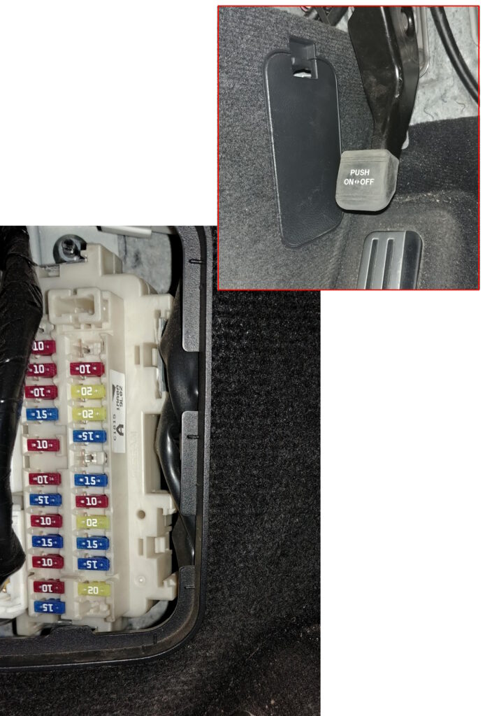
Check the purpose of the elements with your diagram on the back of the block cover.
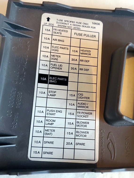
Diagram

Assignment
| 1 | 15A Heated Front Seats |
| 2 | 10A Air Bag Diagnostic Sensor Unit, Occupant Classification System Control Unit |
| 3 | 10A Headlamp Leveling Motor (Right and Left), Shift Lock Relay, Automatic Cruise Control (ASCD) Brake Switch, Intelligent Cruise Control (ICC) Brake Switch, Adaptive Front Lighting (AFS) Control Unit, AFS Switch, Data Connector, LDW Switch, Sonar Control Unit, Lane Departure Warning Buzzer, Instrument Cluster/A/C Unified Amplifier, Heated Seats Relay, Audio/Video Control Unit, Sonar Off Switch, Surround View Camera Control Unit, Buzzer, Telephone Adapter, Compressor, Auto-Dimming Interior Mirror, Lane Keeping Camera Unit, Brake Light Switch, Warning System Switch, Ionizer, Exhaust Gas/Exterior Odor Sensor |
| 4 | 10A Instrument Cluster, Reversing Light Relay |
| 5 | – |
| 6 | 10A Key Slot, Lane Departure Warning Buzzer, Data Port, Unified Instrument Cluster and Air Conditioner Amplifier, Rear Seatback Power Return Control, Rear Seatback Release Relay (Left), Rear Seatback Release Relay (Right), Clock, Auto-Dimming Interior Mirror, Around View Camera Control Module, Display Unit, Phone Adapter, Satellite Radio Tuner, Daytime Running Light Relay, Instrument Cluster |
| 7 | 10A Brake Light Switch, BCM (Body Control Module), Intelligent Cruise Control (ICC) Brake Hold Relay |
| 8 | 20A BOSE Amplifier |
| 9 | 10A Key Slot, Pushbutton Ignition Switch |
| 10 | 10A Seat Position Memory Switch, Automatic Power Positioning Control Module, Driver Seat Control, Outside Rearview Mirror, BCM (Body Control Module) |
| 11 | 10A Instrument Cluster, All-Wheel Drive (AWD) Control Module, Unified instrument cluster, air conditioning amplifier |
| 12 | – |
| 13 | 10A Heated outside mirrors |
| 14 | 20A Heated rear window |
| 15 | 20A Heated rear window |
| 16 | – |
| 17 | – |
| 18 | 15A Front power outlet (cigarette lighter) |
| 19 | 10A Instrument cluster, unified instrument cluster, and air conditioning amplifier, display, multifunction switch, AV control unit, iPod adapter, BCM (body control module), sonar control unit, phone adapter, camera control unit, remote rearview mirror switch, satellite radio tuner, around view monitor control unit |
| 20 | 15/20A Console power outlet |
| 21 | 15A Blower motor |
| 22 | Blower motor |
| Relay | |
| R1 | Ignition |
| R2 | Rear Window Defogger |
| R3 | Accessory |
| R4 | Front Fan |
Fuses 18 and 20 are control the cigarette lighter.
Engine compartment
In the engine compartment, in the rear part on the passenger side, next to the battery, there may be 3 fuse boxes located.

Fuse box 1
Location

Photo example

Diagram

Designation
| 31 | Horn Relay, Generator |
| 32 | Rear Seat Back Power Return Control, Rear Seat Back Release Relay (Left), Rear Seat Back Release Relay (Right) |
| 33 | All-Wheel Drive (AWD) Control Module |
| 34 | Audio Control Module, AV System, iPod Adapter, Surround View Monitor Control Module, Subwoofer, Camera Control Module, Phone Adapter, Satellite Radio Tuner, Subwoofer |
| 35 | Heated Seat Relay |
| 36 | Transmission Control Module (TCM) |
| 37 | Horn Relay 2 |
| 38 | Horn Relay 2 |
| F | Cooling Fan Relay |
| G | Ignition Relay (Fuses: “2”, “3”, “4”), IPDM Control Module |
| H | Fuses: “61”, “63” |
| I | – |
| J | – |
| K | BCM (Body Control Module), Circuit Breaker (Automatic Drive Positioning Control Module), Driver Seat Control, Lumbar Support Switch) |
| L | ABS |
| M | ABS |
| N | 2013–2017: Variable Stroke and Lift Valve Control (VVEL) Motor Relay |
| O | |
| Relay | |
| R1 | Horn |
| R2 | Gearshift lock |
Fuse box 2

Diagram from the covery

Diagram

Allocation
| 41 | 15A Fuel Pump Relay |
| 42 | 10A Cooling Fan Relay |
| 43 | 10A Snow Mode Switch, Transmission Control Module (TCM) |
| 44 | 10A Injectors, Engine Control Module (ECM), Body Control Module (BCM) |
| 45 | 10A ABS, Integrated Cruise Control (ICC), Steering Angle Sensor, Yaw Rate/Side G Sensor, Power Steering Control Module, All-Wheel Drive (AWD) Control Module, Brake Power Control Module, Blind Spot Warning (BSW) Control Module, Side Radar (Left/Right) |
| 46 | 15A Air-Fuel Ratio Sensors, Heated Oxygen Sensors |
| 47 | 10A Combination Switch |
| 48 | 10A Steering Column Lock Relay |
| 49 | 10A Air Conditioner Relay |
| 50 | 15A Engine Control Module Relay (Intake Valve Timing Solenoid Valve, Condenser, Ignition Coils, ECM, MAF Sensor, ECM EVAP Canister Purge Volume, Magnetic Retarder Exhaust Valve Timing Control, EVAP Canister Vent Control Valve, Variable Valve Timing and Lift (VVEL) Control Module |
| 51 | 15A Throttle Actuator Motor Relay |
| 52 | 10A Front Combination Light |
| 53 | 10A Rear Combination Light, License Plate Light, VDC Switch, Adaptive Front Lighting System (AFS) Switch, LDW Switch, Combination Switch (Spiral Cable), Clock, Audio/Video Control Module, Glove Box Light, Control Unit, Sonar Off Switch, Around View Monitor Control Module, Power Switch (Left and Right), Snow Mode Switch, Heated Seats (Driver and Passenger Sides), Remote Rearview Mirror Switch, Roof Module (Console Lamp), Hazard Warning Switch, Front Power Outlet, IBA Switch, Multi-Function Switch |
| 54 | 10A Left High Beam Headlight |
| 55 | 10A Right High Beam |
| 56 | 15A Left Low Beam |
| 57 | 15A Right Low Beam |
| 58 | 15A 2007–2012: Fog Light Relay |
| 10A 2013–2015: Fog Light Relay | |
| 15A 2016–2017: Front Fog Light Relay | |
| 59 | 10A 2016–2017: Daytime Running Light Relay |
| 60 | 30A Front Wiper Relay |
Fuse box 3
This high power fuse block is attached to the positive terminal of the battery.
Diagram

Decoding
- A – 140A Generator, Fuses: “B”, “C”
- B – 100A Fuses: “F”, “H”, “I”, “K”, “L”, “M”, “31”, “32”, “33”, “34”, “35”, “36”, “37”, “38”
- C – 80A Ignition Relay (Fuses: “41”, “42”, “43”, “44”, “45”, “46”, “47”), Fuse: “48”, “50”, “51”
- D – 60A Headlamp High Relay (Fuses: “54”, “55”), Headlamp Low Relay (Fuses: “56”, “57”), Tail Lamp Relay (Fuses: “52”, “53”), Fuses: “58”
- E – 80A Accessory Relay (Fuses: “18”, “19”, “20”), Rear Window Defogger Relay (Fuses: “13”, “14”, “15”), Blower Relay (Fuses: “21”, “22”), Fuses: “5”, “6”, “7”, “9”, “10”, “11”
Fuse box 4
Another block with fuses and relays is installed separately.

Diagram

Appointment
| 61 | 10 A, accelerator pedal actuator |
| 62 | – |
| 63 | 10 A, brake booster control unit |
| Relay | |
| R1 | 2013–2015: Cooling Fan |
| 2016–2017: Daytime Running Lights | |
| R2 | Intelligent Cruise Control (ICC) Brake Hold |
| R3 | – |
| R4 | Horn (No. 2) |
We also have a video on this topic on our channel. Watch and subscribe.
If you have anything to add, please write in the comments.
Hi,
Thank you for your generosity in publishing this video.
A month ago, I bought Infiniti 2017 QX50. I found out now that my Steering Wheel Joystick is not working.
If I identified correctly the fuse box is 2 and fuse 45 in Assignment List: It seems that there are few functions aside from the power steering control and they are all working.
What is your take, please?
Thank you,
ADP