The Infiniti M35 and Infiniti M45 were produced in 2004, 2005, 2006, 2007, 2008, 2009, and 2010 and had the model code Y50. This publication describes the fuses and relays for the Infiniti M35 and M45, including block diagrams, their locations, and photo examples. We’ll highlight the fuse responsible for the cigarette lighter.

The purpose of fuses and relays may differ from that described and depends on the year of manufacture and the level of electrical equipment in your vehicle.
Contents
Passenger compartment
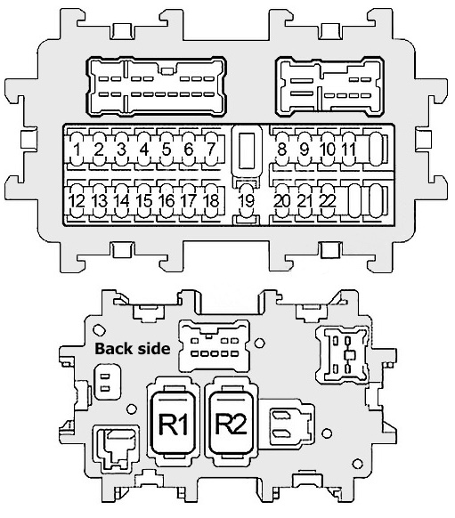
In the car’s interior, the fuse and relay box is located under the instrument panel, on the pillar, on the driver’s side, and is covered with a protective cover.

Check the purpose of the elements with your diagram on the back of the block cover.

Diagram
Assignment
| 1 | 15A Body Control Module (BCM), Engine Control Module (ECM), Injectors, Power Windows, Central Locking, Turn Signals, Hazard Warning Lights, Interior Light, Sunroof |
| 2 | – |
| 3 | – |
| 4 | – |
| 5 | 15A Front Power Outlet, Rear Power Outlet |
| 6 | 10A Combination Switch, Unified Meter and A/C Amplifier, Rear Seat Multimedia System, AV Module, Digital Radio Receiver, Tel. Adapter, Front Display, CD Changer, iPod Adapter, Camera Control Module, BOSE Amplifier, DVD Player, Video Distributor, Rear Display, Body Control Module (BCM), Smart Key, Instrument Cluster, Interior Light |
| 7 | 15A Cigarette Lighter |
| 8 | 10A Heated Mirrors |
| 9 | – |
| 10 | 15A Blower Motor |
| 11 | 15A Blower Motor |
| 12 | 10A Intelligent Cruise Control (ICC), Lane Departure Warning (LDW), Unified Meter and A/C Amplifier, Diagnostic Connector, Shift lock relay, A/C compressor, AV module, Tel adapter, Smart Key system, ASCD cruise control, cooling fan relay, rear sunshade, electrochromic rearview mirror, rear window defogger relay, adaptive front lighting (AFS), headlight range control, tire pressure monitoring system, windshield wiper relay |
| 13 | 10A Airbags |
| 14 | 10A Instrument cluster, reverse lamp relay, AV module, camera control unit |
| 15 | 10A Pre-crash seat belt tensioner system |
| 16 | – |
| 17 | 15A BOSE amplifier |
| 18 | 15A BOSE amplifier |
| 19 | 10A Diagnostic connector, Unified Meter and A/C Amplifier, electrochromic rearview mirror, garage door opener (Homelink), compass, rain sensor |
| 20 | 10A Brake lamp switch, Intelligent Cruise Control (ICC), Smart Key system |
| 21 | 10A Instrument cluster, Body Control Module (BCM), power windows, central Lock, driver position adjustment system, power seats, turn signals, hazard warning lights, interior lighting, sunroof |
| 22 | 10A key slot, push-button start, smart key system, buzzer, power distribution unit (PDU) |
Fuses 5 and 7, rated at 15A, control the cigarette lighter.
On the back of the unit are: R1 – Heater relay and R2 – Auxiliary relay.
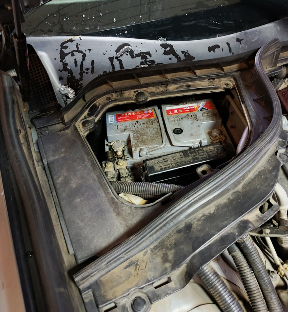
Engine compartment
In the engine compartment, in the rear part on the passenger side, next to the battery, there may be 4 fuse boxes located.
Fuse Box 1
Photo – diagram

Diagram

Designation
| 31 | 20A Rear Axle Steering (RAS) |
| 32 | 10A Daytime Running Lights |
| 33 | 10A All-Wheel Drive |
| 34 | 10A Transmission Control Module (TCM) |
| 35 | 15A Horn Relay |
| 36 | 10A Generator |
| 37 | 15A Combination Switch, AV Module, Digital Radio Receiver, Tel Adapter, Front Display, CD Changer, iPod Adapter, Camera Control Module, DVD Player, Video Distributor, Rear Display, Anti-Theft Alarm Indicator |
| 38 | 15A Heated Seat Relay |
| F | 50A Body Control Module (BCM), Power Windows, Central Locking, Power Seats, Direction Indicators, Hazard Warning, Interior Light, Sunroof, Driver Position Adjustment System |
| G | 30A Pre-Crash Belt Tensioner System |
| H | 30A Ignition Power Distribution Unit (PDU) |
| I | 50A Cooling Fan Relay |
| J | 50A ABS/VDC/TCS |
| K | 30A ABS/VDC/TCS |
| L | – |
| M | 40A Starter, Power Distribution Unit (PDU) |
| Relay | |
| R1 | Horn |
| R2 | Reverse lights |
Fuse Box 2

Installed behind the battery and covered with a protective cover.

Diagram

Allocation
| 71 | 15A IPDM CPU, Parking Light Relay (Parking Light, License Plate Light, Instrument Panel Light, Rear Sunshade) |
| 72 | 10A Right Headlight (High Beam) |
| 73 | 30A Windshield Wiper Relay |
| 74 | 10A Left Headlight (High Beam) |
| 75 | 20A Rear Window Defogger Relay |
| 76 | 15A Right Headlight (Low Beam) |
| 77 | 20A Engine Control Module (ECM) Relay (ECM, Ignition Coils, Capacitor, Intake Valve Timing Control Solenoid Valve, Exhaust Valve Timing Control Magnet Retarder (VQ35HR), Mass Air Flow Sensor, EVAP Vent Valve, Intake Valve Timing Clutch Position Sensor (VK45DE), Crankshaft Position Sensor (VK45DE), Camshaft Position Sensor (VK45DE), Variable Intake Manifold Runner System (VK45DE) |
| 78 | 15A IPDM CPU |
| 79 | 10A Air Conditioner Relay |
| 80 | 20A Rear Window Defogger Relay Glass |
| 81 | 15A Fuel Pump Relay |
| 82 | 10A Intelligent Cruise Control (ICC), Steering Angle Sensor, ABS/VDC/TCS Control Unit, Yaw Rate and Acceleration Sensor, Power Steering Control Unit, Rear Axle Steering (RAS), All-Wheel Drive (AWD) |
| 83 | 10A Transmission Control Module (TCM), Snow Mode |
| 84 | 10A Windshield Wiper Motor, Windshield Washer |
| 85 | 15A Air-Fuel Ratio Sensors, Oxygen Sensors |
| 86 | 15A Left Headlight (Low Beam) |
| 87 | 15A Throttle Relay |
| 88 | 15A Front Fog Light Relay |
| 89 | – |
| Relay | |
| R1 | Engine Control Unit |
| R2 | High Beam |
| R3 | Low Beam |
| R4 | Starter |
| R5 | Ignition |
| R6 | – |
| R7 | – |
| R8 | Heated Seats |
| R9 | Throttle Valve |
| R10 | Fuel Pump |
| R11 | Front Fog Light |
Fuse Box 3

Diagram
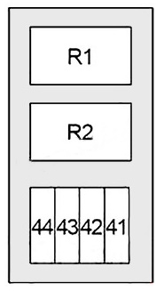
Appointment
| 41 | 15A Passenger Seat Climate Control |
| 42 | 15A Driver Seat Climate Control |
| 43 | – |
| 44 | – |
| Relay | |
| R1 | Climate-controlled seats |
| R2 | Intelligent Cruise Control (ICC) |
Fuse box 4
This high power fuse block is attached to the positive terminal of the battery.

Decoding
| A | 140A Alternator (or AWD), Fuses “B”, “C” |
| B | 100A Fuses “31”, “32”, “33”, “34”, “35”, “36”, “37”, “38”, “F”, “G”, “H”, “I”, “J”, “K”, “M” |
| C | 80A High Beam Relay (Fuses “72”, “74”), Low Beam Relay (Fuses “76”, “86”), Fuses “71”, “73”, “75”, “87”, “88” |
| D | 60A Auxiliary Relay (Fuses “5”, “6”, “7”), Heater Relay (Fuses “10”, “11”), Fuses “17”, “18”, “19”, “20”, “21”, “22”, “41”, “42” |
| E | 80A Ignition Relay (A/C Relay, Relay windshield wiper, windshield wiper speed relay, fuses “81”, “82”, “83”, “84”, “85”), fuses “77”, “78”, “79”, “80” |
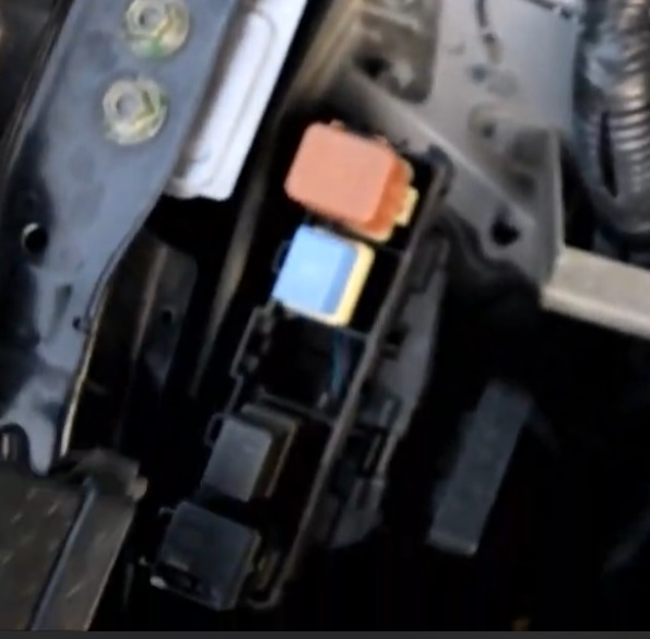
Relay box
Located next to the washer fluid reservoir.
Photo example
Relay diagram from the block cover

Description
- RAD FAN (Radiator Fan)
- WIPER (Wiper)
- HORN 2 (Horn 2)
- DTRL (Daytime Running Lights)
- SHIFT LOCK (Shift Lock)
- RR DEF (Rear Window Defroster)
We also have a video on this topic on our channel. Watch and subscribe.
If you have anything to add, please write in the comments.