The second-generation Infiniti QX50 was produced in 2018, 2019, 2020, 2021, 2022, 2023, 2024, and 2025 with the model code J55. The same applies to the Infiniti QX55. In this publication, we will describe the fuses and relays for the second-generation Infiniti QX50, including fuse box diagrams, their locations, and photo examples. We will highlight the fuse responsible for the cigarette lighter.

The purpose of fuses and relays may differ from that described and depends on the year of manufacture and the level of electrical equipment in your vehicle.
Passenger compartment

In the car’s interior, the fuse box is located on the left end of the dashboard behind a protective cover.
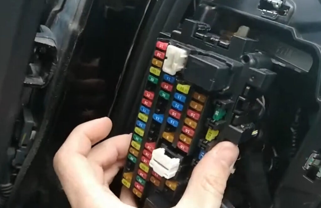
Check the purpose of the elements with your diagrams on the block cover.
Diagram

Assignment
| (BAT) ELEC PARTS | 10A Battery Electrical |
| HEATED STRG | 10A Heated Steering Wheel |
| 4WD | 5A All Wheel Drive |
| P/WDW RR RH | 20A Rear Right Power Window |
| AUTO BACK DOOR | 30A Power Tailgate |
| TURN & HAZARD | 10A Turn Signals and Hazard Lights |
| ROOM LAMP | 10A Interior Light |
| DOOR LOCK RR | 15A Rear Door Locks |
| DOOR LOCK FR | 20A Front Door Locks |
| RR WIPER | 15A Rear Wiper |
| P/WDW RR LH | 20A Rear Left Power Window |
| E-PKB RH | 30A Electric Handbrake Right Circuit |
| P/WDW FR RH | 20A Front Right Power Window |
| SHIFT BY WIRE-1 | 10A Electronic Gear Selector (Circuit 1) |
| E-PKB LH | 30A Electric Handbrake Left Circuit |
| BCM | 5A Body Electronics Module |
| P/WDW FR LH | 20A Front Left Power Window |
| HEATED SEAT DR | 15A Heated Driver’s Seat |
| ATR CONT | 10A Traction Control/Stability Control |
| BLOWER MOTOR | 30A Blower Motor |
| HEATED SEAT AS | 15A Heated Passenger Seat |
| WASH PUMP | 10A Washer Pump |
| ADAS | 10A Cameras/Radar, Assistants |
| USB CHARGE | 10A USB Charger |
| POWER SOCKET | 20A Cigarette Lighter |
| HEATED MIRROR | 10A Heated Mirrors |
| RR DEF | 30A Heated Rear Window |
| (ACC) ELEC PARTS | 10A Electrical System via ACC |
| HUD | 5A Head-Up Display |
| BOSE AMP-MINI | 20A Bose Amplifier (mini) |
| BOSE AMP-1 | 15A Bose Amplifier (Channel 1) |
| BOSE AMP-2 | 15A Bose Amplifier (Channel 2) |
| AUDIO | 10A Audio System |
| (BAT) ELEC PARTS | 5A Electrical System (Auxiliary Circuit from Battery) |
| AIR BAG | 10A Airbags |
| METER | 5A Instrument Cluster |
| STOP LAMP | 10A Brake Lights |
| (IGN) ELEC PARTS | 5A Electrical System after Ignition |
| SHIFT BY WIRE-2 | 5A Electronic Shift Selector (Circuit 2) |
| (IGN) ELEC PARTS | 10A Engine/Ignition Circuits |
| VDC CONT | 5A Stability Control (VDC/ESP) |
The fuse marked as POWER SOCKET is responsible for the operation of the cigarette lighter.
Engine compartment
In the engine compartment, the fuse and relay boxes are located on the left side next to the battery.
Fuse box 1

Diagram from covery

Diagram

Designation
| 51 | 10A Active Grille Shutter, Engine Control Module |
| 52 | 15A Engine Control Module, EVAP Canister Purge Volume Control Solenoid Valve, Engine Coolant Bypass Valve Control Solenoid Valve, Fuel Heater and Water in Fuel Level Sensor, High Pressure Fuel Pump, Condenser, Ignition Coils, Exhaust Valve Timing Control Solenoid Valve, Intake Valve Timing Control Solenoid Valve, Fuel Injector Relay, High Pressure Fuel Pump Relay, Mass Air Flow Sensor, Heated Oxygen Sensor, Turbocharger Waste Gate Control Solenoid Valve, Air Fuel Ratio Sensor, Fuel Flow Actuator, Turbocharger Boost Control Solenoid Valve, Intake Valve Timing Intermediate Solenoid Valve, Intake Valve Timing Control Solenoid Valve, Turbocharger Bypass Control Valve, Engine Oil Pressure Control Solenoid Valve |
| 53 | 15A MR: Throttle Control Motor Relay |
| 54 | 10A Engine Control Module, Engine Coolant Bypass Valve Control Solenoid Valve, Intake Valve Timing Control Solenoid Valve, Engine Oil Pressure Control Solenoid Valve, Exhaust Valve Timing Control Solenoid Valve, Turbocharger Bypass Valve Control Solenoid Valve, Intake Manifold Runner Control Valve |
| 55 | 15A Engine Control Module, Heated Oxygen Sensor, Thermostat Heater Control Solenoid Valve, Glow Control Unit, Turbocharger Boost Control Solenoid, Air Fuel Ratio Sensor, Fuel Flow Actuator, Intake Manifold Runner Control Valve |
| 56 | 15A Engine Control Module, Steering Lock Unit |
| 57 | 15A Air Conditioner Relay |
| 58 | 10A Engine Control Module, Engine Restart Relay |
| 59 | – |
| 60 | 30A Front Wiper Hi/Lo Relay |
| 61 | 20A Fuel Pump Relay |
| 62 | – |
| 63 | 10A Transmission Control Module (TCM), Primary Speed Sensor, Output Speed Sensor, Transmission Range Switch, Input Speed Sensor, Ipdm E/R, Secondary Speed Sensor |
| 64 | – |
| 65 | 5A Engine Control Module, Steering Lock Unit |
| 66 | 10A Airbags, ABS system |
| 67 | 10A Headlamp Aiming Motor, Compressor, Transmission Range Switch, Front Window Defogger RH Relay, Front Window Defogger LH Relay, Reverse / Neutral Position Switch, Back-Up Lamp Switch, Neutral Position Switch |
Fuse box 2

Diagram from covery

Allocation
| VDC CONT | 20A VDC/ESP Stabilizer Unit |
| POSITION LAMP (DRL) | 10A Side Lights / DRL |
| FUEL HIGH PUMP | 15A High Pressure Fuel Pump |
| SHIFT BY WIRE MOTOR A | 20A Electronic Gear Selector Motor (Circuit A) |
| SHIFT BY WIRE CONT | 10A Electronic Gear Selector Control |
| POWER SOCKET | 15A Socket / Cigarette Lighter |
| TOWING | 30A Towbar / Trailer Circuit |
| INJECTOR 1 | 15A Injectors 1st Circuit |
| INJECTOR 2 | 15A Injectors 2nd Circuit |
| DCA PEDAL | 10A Accelerator Pedal (Sensor) |
| CVT CONT | 10A CVT Control |
| ANTI-THEFT HORN | 15A Alarm Siren |
| HORN | 15A Horn |
| SHIFT BY WIRE MOTOR B | 20A Gear Selector Motor (Circuit B) |
| WIPER DEICER | 15A Heated Wiper Zone |
We have posted a video on our YouTube channel. Watch and subscribe.
If you still have questions or know how to make the article better, write in the comments.