The Hyundai Matrix subcompact van is also known in some countries as the Hyundai Lavita. Produced mainly with gasoline engines 1.5 1.6 1.8 liters. Years of production: 2001, 2002, 2003, 2004, 2005, 2006, 2007, 2008, 2009 and 2010. During this time, the matrix was restyled 2 times. In this material you will find a description of Hyundai Matrix fuses and relays with box diagrams and photo examples of location. Note the cigarette lighter fuse. We will also show the location of all electronic control units.

Depending on the region of delivery and the year of manufacture, different designs of fuse and relay boxes are possible. Check the assignment with your diagrams on the back of the protective cover.
Locations
General layout of electronic control units

Appointment
| 1 | ABS electronic control unit |
| 2 | Side impact sensor, left – B-pillar |
| 3 | Side impact sensor, right – B-pillar |
| 4 | Anti-theft alarm siren – partition |
| 5 | Audible Warning / Buzzer – Behind the dashboard fuse / relay box |
| 6 | Accumulator battery |
| 7 | Diagnostic connector (DLC) – under the dash |
| 8 | Daylight Control Module – Inner Wing |
| 9 | Electronic engine control unit – lower protection panel |
| 10 | Fuse / relay box, engine compartment 1 |
| 11 | Fuse / relay box, engine compartment 2 (Diesel) |
| 12 | Fuse / Relay Box, Engine Compartment W (Diesel) |
| 13 | Fuse / relay box, instrument panel |
| 14 | Heater fan motor resistor – next to the heater fan motor |
| 15 | Beep (upper) |
| 16 | Beep (bottom) |
| 17 | Inertia Fuel Cut-Off Switch – Behind Battery |
| 18 | Immobilizer control unit – behind the dashboard fuse / relay box |
| 19 | Multifunction control unit – behind the dashboard fuse / relay box – Anti-theft functions, central locking, heated rear window, ignition key buzzer, interior lighting / delayed off, seat belt warning system, windshield wiper / washer |
| 20 | Sunroof Motor Relay – Headlining |
| 21 | Electronic control unit SRS – under the center console |
| 22 | Electronic control unit for gearbox – automatic transmission – behind the dashboard, on the left |
| 23 | Rear Wiper Relay – Luggage Compartment LH |
Dashboard fuse box

Located at the bottom of the dashboard. Remove the protective cover for access.

Diagram

Relay
- Reserve
- Central locking relay (unlocked)
- Alarm relay
- Reserve
- Central locking relay
- Power window relay
- Anti-theft relay
- Anti-theft alarm siren relay
- Heated rear window relay
- Turn signal interrupter relay
- Heater blower motor relay
Several versions of the fuse compartment are possible.
Diagram

Designation
| RR HTD | 30A Rear window defogger relay |
| STOP | 10A Brake light relay, power window relay |
| D/LOCK | 15A Relay for locking (unlocking) doors, ETASM, sunroof relay |
| HAZARD | 10A Burglar Alarm Relay, Alarm Relay |
| AUDIO | 10A Car radio |
| C/LIGHT | 15A Cigarette lighter |
| A/B | 10A Airbag control unit |
| A/В IND | 10A Airbag warning lamp |
| T / SIG | 10A Hazard Switch, Seat Belt Timer, Instrument Panel, ABS Control Unit, Excitation Resistor, Washer Pump Drive |
| ECU | 15A ECM, vehicle speed sensor, TCM, ignition coil |
| ETACS | 10A ETASM, automatic transmission selector |
| RRWPR | 10A Rear wiper motor, rear wiper relay |
| START | 10A Starter relay |
| FRTWPR | 20A Wiper relay, washer pump motor, wiper and rear window defroster timer |
| S/HTD | 15A Switch for heating the left (right) front seat |
| P/OUTLET | 25A Front (rear) socket for connecting external consumers |
| IG2 | 10A ETASM, power window relay, rear window defogger relay, sunroof relay, headlight relay, heating and air conditioning fan relay |
| O / S MRR | 10A Exterior mirror switch, rear fog lamp relay |
The fuse responsible for the front cigarette lighter is designated as C / LIGHT, and for the additional sockets P / OUTLET.
Engine compartment
Main box
It is located next to the battery under the protective cover.

Example of a diagram from the cover
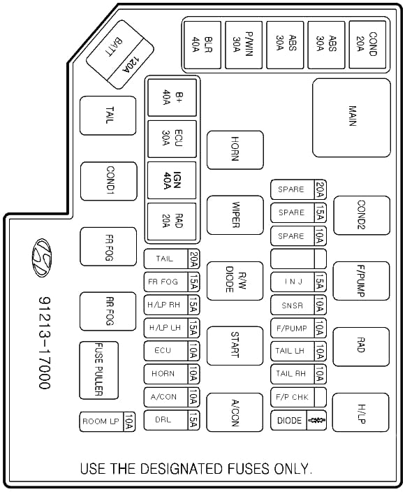
Diagram

Assignment
| 1 (30) | COND – Electro condenser fan |
| 2 (40) | ABS – ESP and anti-lock brakes ABS |
| 3 (40) | ABS – ESP and anti-lock brakes ABS |
| 4 (30) | P / WIN – Electric windows |
| 5 (40) | BLR – Electric heater radiator fan |
| 6 (10) | ABS – Anti lock brake system ABS |
| 7 (15) | INJ – Fuel injectors, ignition coils |
| 8 (10) | SNSR – Sensors of the engine management system |
| 9 (10) | F / PUMP – Fuel pump |
| 10 (10) | TAIL LH – Left tail light, left license plate light |
| 11 (10) | TAIL RH Right tail light, right license plate light |
| 12 N | Rear fog lamp activation diode |
| 13 (120) | WATT – Generator |
| 14 (40) | B + – Air conditioning, heated rear window, brake lights, central locking, anti-theft alarm |
| 15 (30) | ECU – Engine control unit, generator, main relay of the engine management system |
| 16 (40) | IGN – Starter, ignition switch (lock) |
| 17 (30) | RAD – Electro radiator fan |
| 18 (20) | TAIL – Rear lights |
| 19 (15) | FR FOG – Fog lights |
| 20 (15) | H / LP LH – Left headlight |
| 21 (15) | NDR RH – Right headlight |
| 22 (10) | ECU – Engine control unit, generator, main relay of the engine management system |
| 23 (10) | HORN – Sound signal |
| 24 (10) | A / CON – Air conditioner |
| 25 (15) | DRL – Side light control unit |
| 26 (10) | ROOM LP – Car radio, interior lighting, instrument cluster illumination |
| R1 | MAIN – Main relay |
| R2 | COND2 – Relay for electric condenser fan (low speed) |
| R3 | F / P CHK – Fuel pump relay |
| R4 | RAD – Relay, electric radiator fan |
| R5 | H / LP – Relay for headlights |
| R6 | HORN – Horn relay |
| R7 | WIPER – Wiper relay |
| R8 | R / W DIODE – Relay for diode activation (pos. 12) |
| R9 | START – Starter relay |
| R10 | A / CON – Relay for air conditioning |
| R11 | TAIL – Relay for turning on the rear lights |
| R12 | COND1 – Condenser electric fan relay (high speed) |
| R13 | FR FOG – Relay for switching on rear fog lamps |
Additional box
legend

Description
- GLOW – candles
- PTC – additional heater
Anything to add? Write in the comments.
Have a Matrix 2010, centrale lock does niet work. Dashboard fuseren box does not mach with my car.
Where can y find the correct one.
waar zit de zekering voor de centrale lock?