The third-generation Honda HR-V was produced in 2022, 2023, 2024, 2025, 2026, 2027, and 2028. During this time, the model received an update. In Europe, it is also known as the Honda ZR-V. In this post, we will present a description of the Honda HR-V 3G and Honda ZR-V fuses and relays with fuse box diagrams, their locations and photo examples of performance. Select the cigarette lighter fuses.

The purpose of the fuses and relays and their location may differ from those shown and depend on the year of manufacture, the level of electrical equipment and the region where your car was delivered.
Passenger compartment
The fuse and relay boxes in the cabin, is located under the instrument panel on the driver’s side.

Check the information against your diagrams on the block covers or label.

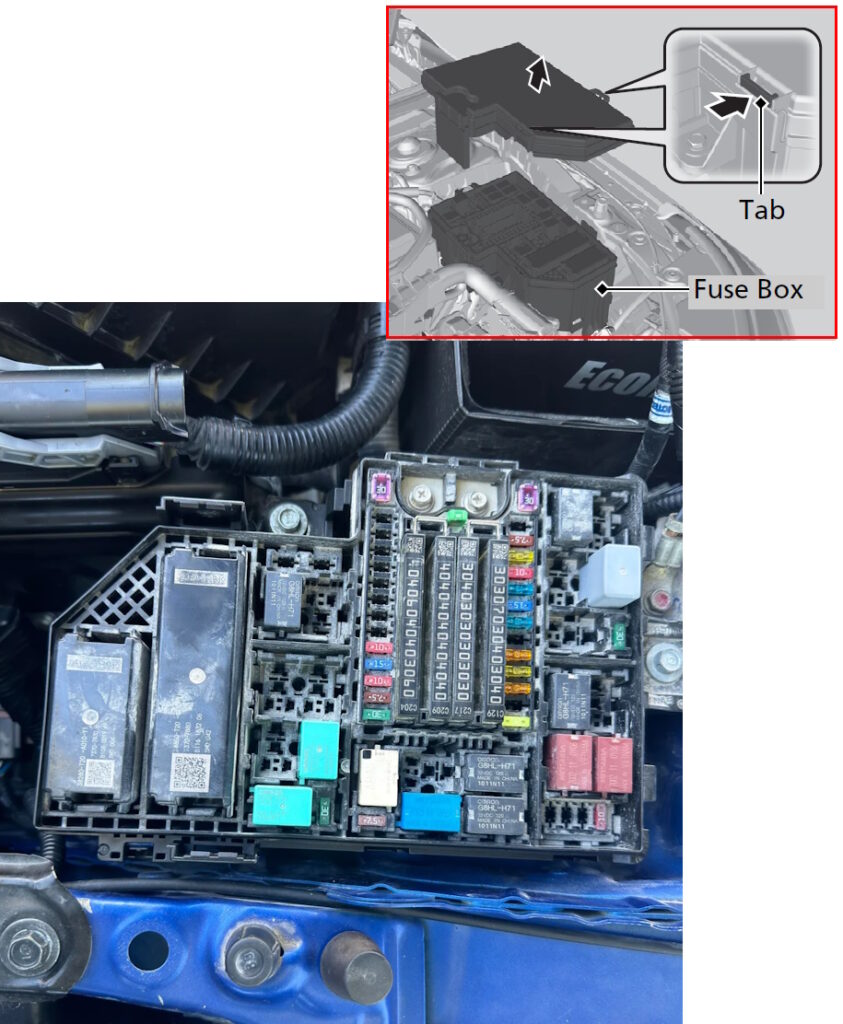
Photo for example

Diagram
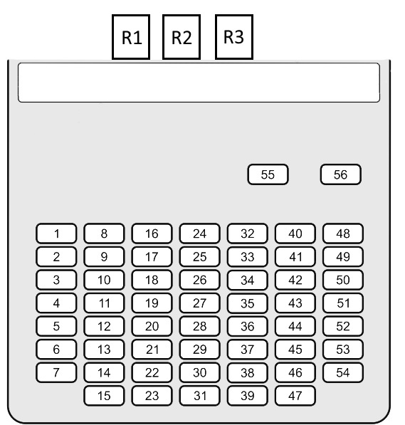
Assignment
| 1 | 20A P/W DR — Driver door power window |
| 2 | 20A P/W AS — Front passenger door power window |
| 3 | 20A P/W RR R — Rear right door power window |
| 4 | 20A P/W RR L — Rear left door power window |
| 5 | 10A OPTION — Optional equipment (depends on vehicle specification) |
| 6 | 10A SRS — Supplemental Restraint System (airbags, pretensioners) |
| 7 | 10A T/G MTR — Fuel lid motor |
| 8 | — |
| 9 | 20A FR ACC SOCKET — Front accessory power socket |
| 10 | 20A DOOR LOCK — Central door locking system |
| 11 | 10A METER — Combination meter / instrument cluster |
| 12 | 10A ST CUT RLY — Starter cut relay |
| 13 | 10A OPTION2 — Optional equipment No.2 |
| 14 | 10A OPTION6 (VB SOL) — VB system solenoid |
| 15 | 10A DR DOOR UNLOCK — Driver door unlock circuit |
| 16 | 20A SUNROOF — Sunroof motor |
| 17 | — |
| 18 | — |
| 19 | — |
| 20 | — |
| 21 | 20A CARGO ACC SOCKET — Cargo area accessory power socket |
| 22 | 10A SMART — Smart Key / keyless entry system |
| 23 | 10A DR DOOR LOCK — Driver door lock circuit |
| 24 | — |
| 25 | 10A IMG — Immobilizer system |
| 26 | 10A SRS — SRS system (secondary circuit) |
| 27 | 10A ACG — Alternator control circuit |
| 28 | 10A ABS/VSA — ABS / Vehicle Stability Assist control |
| 29 | 20A FUEL PUMP — Fuel pump |
| 30 | 10A L SIDE DOOR UNLOCK — Left sliding door unlock |
| 31 | 10A R SIDE DOOR UNLOCK — Right sliding door unlock |
| 32 | — |
| 33 | 10A USB CHG — USB charging power supply |
| 34 | — |
| 35 | — |
| 36 | — |
| 37 | 20A E-PT L — Electric power tailgate (left side) |
| 38 | — |
| 39 | 10A R SIDE DOOR LOCK — Right sliding door lock |
| 40 | 20A P SEAT REC / RR HI — Power seat recline / rear seat heater |
| 41 | 20A P SEAT SLIDE / FR HI — Power seat slide / front seat heater |
| 42 | — |
| 43 | 10A A/C — Air conditioning system |
| 44 | 10A DRL — Daytime Running Lights |
| 45 | 10A ACC — Accessory power circuit |
| 46 | 10A ACC KEY LOCK — Ignition key lock system |
| 47 | 10A L SIDE DOOR LOCK — Left sliding door lock |
| 48 | 20A H/SEAT — Seat heater |
| 49 | — |
| 50 | — |
| 51 | — |
| 52 | 20A E-DPS — Electric Dynamic Power Steering |
| 53 | — |
| 54 | 10A OPTION1 / FUEL LID — Optional equipment / fuel lid actuator |
| 55 | — |
| 56 | — |
Fuses 9 for 20A is responsible for the operation of the front cigarette lighters.
- R1 – Power Window Relay
- R2 – Front Accessory Power Socket Relay
Engine compartment
Under the hood, the fuse and relay box is located next to the battery.
Block cover diagram

Diagram
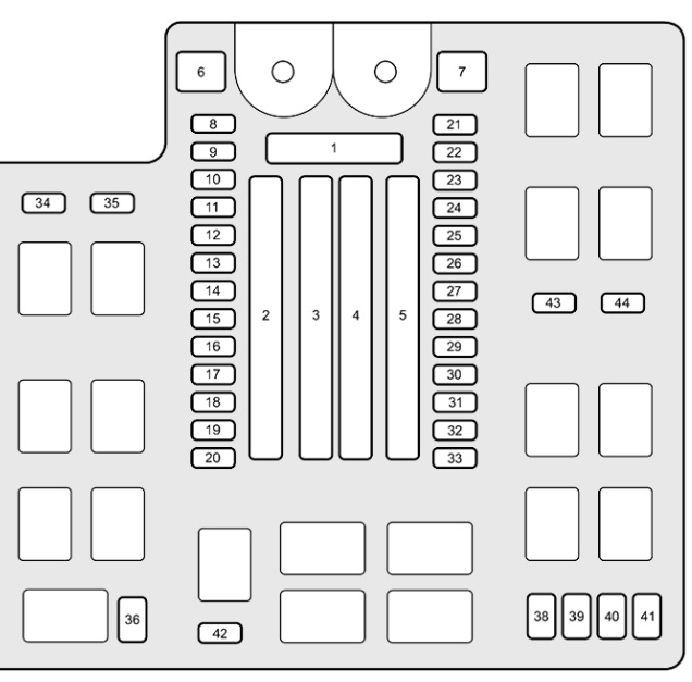
Allocation
Fuses
| 1 | 125A BATTERY — Main battery power supply |
| 2 | 40A ZR-V: A/C PTC1 — Air conditioning PTC heater circuit 1 (ZR-V) |
| 40A Not used | |
| 60A F/BOX OPTION — Fuse box optional power supply | |
| 40A Not used | |
| 40A F/BOX OPTION2 — Fuse box optional power supply No.2 | |
| 3 | 30A Not used |
| 60A F/BOX MAIN — Main interior fuse box power supply | |
| 30A Not used | |
| 30A Not used | |
| 70A Not used | |
| 30A RR DEFROSTER — Rear window defogger | |
| 40A ZR-V: PTG MTR — Power tailgate motor | |
| 30A ZR-V: A/C PTC3 — Air conditioning PTC heater circuit 3 | |
| 40A HTR MTR — Heater blower motor | |
| 4 | 30A ZR-V: ESB — Electronic service brake |
| 40A ABS/VSA MTR — ABS / Vehicle Stability Assist motor | |
| 30A ZR-V: RFC — Rear fan control | |
| 30A ZR-V: P-ACT MTR — Power actuator motor | |
| 30A IG MAIN — Main ignition power supply | |
| 30A ZR-V: OPTION6 — Optional equipment circuit | |
| 30A HR-V (US): IG MAIN2 — Secondary ignition main circuit | |
| 5 | 30A HR-V (US): ST MAGNETIC SW — Starter magnetic switch |
| 30A WIPER — Windshield wiper motor | |
| 70A EPS — Electric power steering | |
| 30A ZR-V: IG MAIN2 — Secondary ignition main circuit | |
| 40A ABS/VSA FSR — ABS/VSA fail-safe relay | |
| 30A/40A HR-V (US): MAIN FAN / ZR-V: F/BOX MAIN2 — Cooling fan or secondary fuse box main supply | |
| 40A F/BOX MAIN2 — Secondary interior fuse box power supply | |
| 6 | 30A HR-V (US): SUB FAN — Cooling sub fan |
| 7 | 40A HR-V (US): BOOSTER MTR — Brake booster motor |
| 8 | 20A/30A ZR-V: AUDIO AMP — Audio amplifier |
| 9 | 20A ZR-V: SUNSHADE — Electric sunshade |
| 10 | 7.5A AUDIO SUB — Audio system sub power |
| 11 | 15A HR-V (US): FR DEICER — Front windshield deicer |
| 12 | 20A ZR-V: SUPER LOCK — Super lock / double lock system |
| 13 | 10A H/STRG — Heated steering wheel |
| 14 | 10A ZR-V: BATT IR — Battery internal relay |
| 15 | 15A ZR-V: H/L ADJ — Headlight level adjustment |
| 16 | 10A MG CLUTCH — A/C compressor magnetic clutch |
| 17 | 15A WASHER — Windshield washer motor |
| 18 | 10A HORN — Horn |
| 19 | 15A BACK UP — Backup / reverse light and memory circuits |
| 20 | 15A AUDIO — Audio system |
| 21 | 20A R/M1 — Relay module No.1 |
| 22 | 15A DBW — Drive-by-wire (electronic throttle) |
| 23 | 20A R/M2 — Relay module No.2 |
| 24 | 10A BACKUP FI-ECU — Engine ECU backup power |
| 25 | 15A IGP — Ignition power |
| 26 | 10A/15A HR-V (US): TCU / ZR-V: DCU — Transmission or drive control unit |
| 27 | 20A LCM L — Left lighting control module |
| 28 | 20A ZR-V: INJ — Fuel injectors |
| 29 | 10A STOP — Brake lights |
| 30 | 20A LCM R — Right lighting control module |
| 31 | 15A IG COIL — Ignition coils |
| 32 | 20A ZR-V: EVTC — Electronic variable timing control |
| 33 | 15A HAZARD — Hazard warning lights |
| 34 | 10A ZR-V: IGA — Ignition signal circuit A |
| 35 | Not used |
| 36 | Not used |
| 37 | 30A Not used |
| 38 | 10A ZR-V: PCU EWP — Electric water pump (power control unit) |
| 39 | 10A ZR-V: P-ACT DRV — Power actuator drive circuit |
| 40 | 7.5A/10A ZR-V: IGB — Ignition signal circuit B |
| 41 | 10A IGPS (LAF) — Ignition power for air-fuel ratio sensor |
| 42 | 10A IG1 MON2 — Ignition line monitoring circuit |
| 43 | Not used |
| 44 | Not used |
Relay
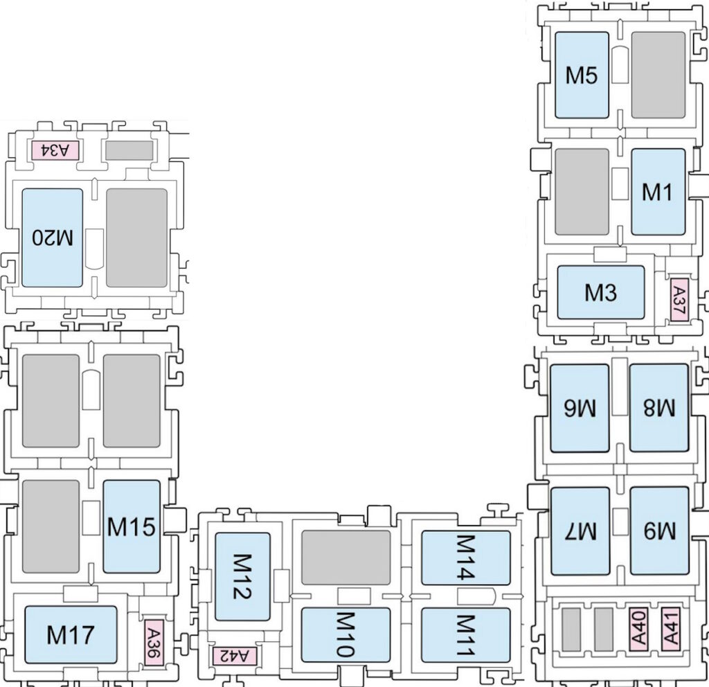
Appointment
| M20 | Radiator Fan Relay |
| M15 | Rear Window Defogger Relay |
| M17 | Blower Motor Relay |
| M12 | A/C Compressor Clutch Relay |
| M10 | PGM-FI Main Relay 2 |
| M11 | Electric Oil Pump Relay |
| M14 | Horn Relay |
| M7 | PGM-FI Main Relay 1 |
| M6 | PGM-FI Subrelay |
| M8 | Injector Relay |
| M9 | Ignition Coil Relay |
| M1 | Fan Control Relay |
| M3 | Heated Steering Wheel Relay |
| M5 | A/C Condenser Fan Relay |
We have also posted a video for this post on our YouTube channel. Watch and subscribe to the channel.
Found a mistake or have something to add – write in the comments.