Honda Odyssey 6 th generation was produced in 2018, 2019, 2020, 2021, 2020, 2023 with body designation RL6. During this time, the model has been restyled. In this post, we will present a description of the fuses and relays for the Honda Odyssey 6 with fuse box diagrams and their locations. Select the cigarette lighter fuse.

The purpose of the fuses and relays may differ from the one shown and depends on the year of manufacture, the level of electrical equipment and the region where your car was delivered.
Contents
Passenger compartment
Fuse boxes on the driver’s side
Under the instrument panel, on the driver’s side, there are two fuse boxes (Block A and B).

Photo example

Diagram
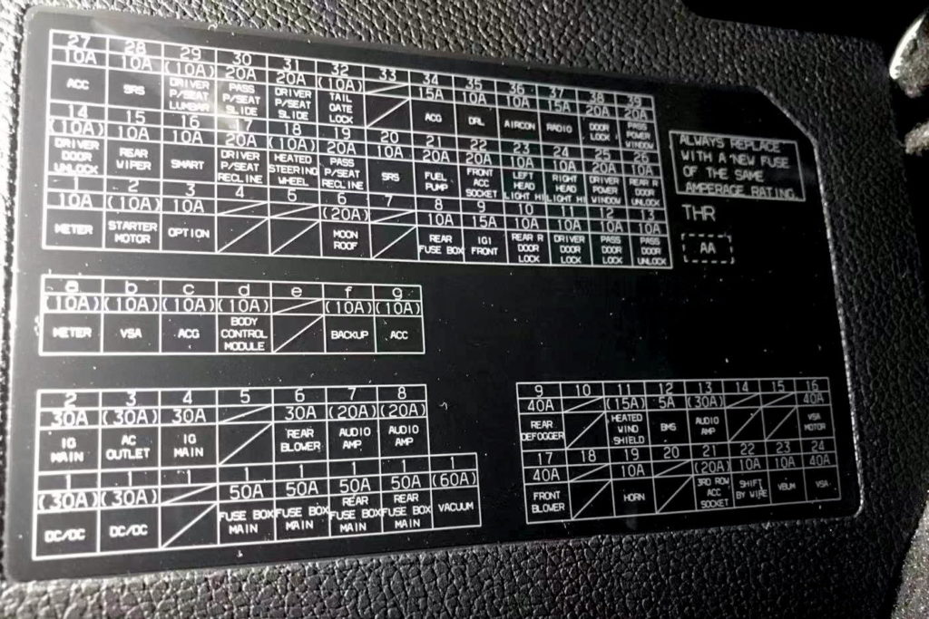
Fuse box A
Description
| 1 | 30A DC/DC2 |
| 1 | 30A DC/DC1 |
| 1 | — |
| 1 | 50A Fuse Box Main1 |
| 1 | 50A Fuse Box Main2 |
| 1 | 50A Rear Fuse Box Main1 |
| 1 | 50A Rear Fuse Box Main2 |
| 1 | 60A Vacuum (optional) |
| 2 | 30A IG Mainl |
| 3 | 30A AC Outlet |
| 4 | 30A IG Main2 |
| 5 | — |
| 6 | 30A Rear Blower |
| 7 | 20A Audio Amp2 (optional) |
| 8 | 20A Audio Amp1 (optional) |
| 9 | 40A Rear Defogger |
| 10 | — |
| 11 | 15A Heated Windshield (optional) |
| 12 | 10A BMS |
| 13 | 30A Audio Amp3 (optional) |
| 14 | — |
| 15 | — |
| 16 | 40A VSA Motor |
| 17 | 40A Front Blower |
| 18 | — |
| 19 | 10A Horn |
| 20 | — |
| 21 | 20A 3rd Row Accessory Power Socket (optional) |
| 22 | 10A Shift By Wire |
| 23 | 10A VBUM |
| 24 | 40A VSA |
The number 3 fuse is responsible for the front cigarette lighter.
Fuse box B
Designation
| 1 | 10A Meter |
| 2 | 10A Starter Motor (optional) |
| 3 | 10A Option |
| 4 | — |
| 5 | — |
| 6 | 20A Moonroof (optional) |
| 7 | — |
| 8 | 10A Rear Fuse Box |
| 9 | 15A IG1 Front |
| 10 | 10A Rear Passenger’s Door Lock |
| 11 | 10A Driver’s Door Lock |
| 12 | 10A Front Passenger’s Door Lock |
| 13 | 10A Front Passenger’s Door Unlock |
| 14 | 10A Driver’s Door Unlock |
| 15 | 10A Rear Wiper |
| 16 | 10A SMART |
| 17 | 20A Driver’s Power Seat Reclining |
| 18 | 10A Heated Steering Wheel (optional) |
| 19 | 20A Front Passenger’s Power Seat Reclining |
| 20 | 10A SRS |
| 21 | 20A Fuel Pump |
| 22 | 20A Front Accessory Power Socket |
| 23 | 10A Left Headlight High Beam |
| 24 | 10A Right Headlight High Beam |
| 25 | 20A Driver’s Power Window |
| 26 | 10A Rear Passenger’s Door Unlock |
| 27 | 10A ACC |
| 28 | 10A SRS2 |
| 29 | 10A Driver’s Power Seat Lumbar Support (optional) |
| 30 | 20A Front Passenger’s Power Seat Sliding |
| 31 | 20A Driver’s Power Seat Sliding |
| 32 | 10A Tailgate Lock (optional) |
| 33 | — |
| 34 | 15A ACG |
| 35 | 35A DRL |
| 36 | 36A A/C |
| 37 | 15/20A Radio |
| 38 | 20A Door Lock Main |
| 39 | 20A Front Passenger’s Power Window |
Relays
- R1 – Front Accessory Power Socket Relay
- –
- R3 – Left Rear Accessory Power Socket Relay
Fuse box on the passenger’s side
On the right side, under the instrument panel, on the rack is another fuse box.

Diagram

Assignment
| a | 10А Meter |
| b | 10А VSA |
| c | 10А ACG |
| d | 10А Body Control Module |
| e | — |
| f | 10А Back Up |
| g | 10А ACC |
Engine compartment
Fuse and relay box
It is located under the hood on the right side and is closed with a protective cover. It will look something like this.

In the top row, in the middle of the fan relay.
Check the information with your diagrams.
An example of a circuit from the block cover

Allocation
| 1 | — |
| 2 | — |
| 3 | — |
| 4 | 10A IG1 VB SOL |
| 5 | 5A VSA/ABS |
| 6 | 30A Wiper |
| 7 | 15A IG1 DBW |
| 8 | 15A TCU |
| 9 | 15A IGP1 |
| 10 | 30A Sub Fan Motor |
| 11 | 30A Rear Driver’s Side Power Window |
| 12 | 30A Ignition Coil/lnjector |
| 13 | 10A TCU 2 |
| 14 | 10A TCU 3 |
| 15 | 30A PDM LT2 |
| 16 | 30A ST CUT |
| 17 | 10A Shutter Grill |
| 18 | 10A Back Up |
| 19 | 10A Stop |
| 20 | 30A PDM LT1 |
| 21 | 30A Rear Passenger’s Side Power Window |
| 22 | 20A ACM |
| 23 | 15A Hazard |
| 24 | 15A Washer |
| 25 | 30A Main Fan Motor |
| 26 | 5A STRLD |
| 27 | 5A IGPS |
| 28 | 10A Stop |
| 29 | 10A Right Headlight Low Beam |
| 30 | 10A Left Headlight Low Beam |
| 31 | 20A Injector |
| 32 | 15A Ignition Coil |
| 33 | 5A FET Module |
Relays
Diagram
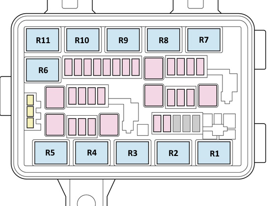
- R1 – Rear Window Defogger Relay
- R2 – Brake Light Relay
- R3 – Electronic Throttle Control System Control Relay
- R4 – A/C Condenser Fan Relay
- R5 – PGM-FI Main Relay 1
- R6 – Rear Window Washer Motor Relay
- R7 – Starter Cut Relay 1
- R8 – Starter Cut Relay 2
- R9 – Radiator Fan Relay
- R10 – Fan Control Relay
- R11 – Windshield Washer Motor Relay
Power fuse box
On the positive terminal of the battery, the main power unit is installed, made in the form of high power fuse links.

Diagram

Appointment
- a 150A – Battery Main
- b 70A – FET
- c 70A – R/B Main 1
- d 70A – R/B Main 2
- e 70A – EPS
- t 60A – VAC
Luggage compartment
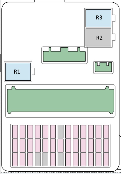
It is located on the right side of the luggage compartment, also closed with a protective cover.


Diagram

Decoding
- 10A – Rear Driver’s Side Door Lock
- 20A – Passenger’s Side Power Sliding Door Closer (optional)
- 20A – Power Tailgate Closer Motor (optional)
- 20A – Cargo Area’s Accessory Power Socket
- 10A – Fuel Fill Door
- —
- 20A – Driver’s Side Power Sliding Door Closer (optional)
- —
- —
- —
- —
- —
- —
- 30A – Passenger’s Side Power Sliding Door Motor (optional)
- —
- 40A – Power Tailgate Motor (optional)
- —
- —
- 30A – Driver’s Side Power Sliding Door Motor (optional)
Relay
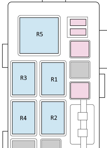
- R1 – Left Sliding Door Lock Relay
- R2 – Cargo Area Accessory Power Socket Relay
- R3 – Left Sliding Door Unlock Relay
- R4 – Fuel Fill Door Lock Actuator Relay
- R5 – HondaVAC Motor Relay
There is something to add – write in the comments.
Where is the horn relay location in honda odyssey 2022
Please describe the relays. They are never described in any article. I really need to have a diagram that includes a description of the relays.
Done! Check it.