Chevrolet TrailBlazer 2nd generation was available in 2011, 2012, 2013, 2014, 2014, 2015, 2016, 2016, 2017, 2018 and 2019. Also known as Holden Trailblazer 2. In this article you can find information about Chevrolet TrailBlazer 2 fuses and relays with fuse box diagrams, their locations and photo examples of performance. Let’s highlight the cigarette lighter fuse.

The design of the fuse and relay boxes and the assignment of fuses and relays may differ from that shown and depends on the year of manufacture and the level of electrical equipment in your vehicle.
Engine compartment
Under the bonnet in the engine compartment, the main fuse and relay box is located on the left-hand side, next to the battery.

Check the assignment of the elements with your diagrams on the back of the protective cover.

Diagram

Designation
| 1 | 10A Air conditioner compressor clutch |
| 2 | 15A Bodywork control unit (6) – reversing |
| 3 | 15A Reserve |
| 4 | 10A Rear lock |
| 5 | 15A Horn |
| 6 | 15A Front fog lamp |
| 7 | 10A High beam, left headlamp |
| 8 | 10A High beam, right headlamp |
| 9 | 10A Reserve |
| 10 | 15A Transmission relay (3) |
| 11 | 20A Diesel engine ECU (1) 15A Petrol engine ECU (1) |
| 12 | 10A Transmission relay (1) |
| 13 | 10A Transmission relay (2) |
| 14 | 15A Transmission relay (4) |
| 15 | 15A Running/starting relay |
| 16 | 15A Traction control system control unit |
| 17 | 10A Transfer case control unit and headlamp corrector |
| 18 | 10A Power supply unit air conditioning and airbag control unit |
| 19 | 20A Fuel pump |
| 20 | 5A Reserve |
| 21 | 30A Heated rear window |
| 22 | 15A Heated exterior mirrors |
| 23 | 15A Auxiliary heater |
| 24 | 20A Rear window wiper |
| 25 | 10A Windscreen and rear window washer pump |
| 26 | 10A Rear parking assist |
| 27 | 5A Electronic body systems control unit |
| 28 | – |
| 29 | 30A ABS module |
| 30 | 10A Burglary protection system relay |
| 31 | 15A Body electronic systems control unit |
| 32 | 15A Engine control unit (battery) |
| 33 | 10A Common, switch-on |
| SB01 | 50A ABS module pump |
| SB02 | 30A Transfer case control unit (four-wheel drive) |
| SB03 | 60A Glow plug module |
| SB04 | 20A Rear power outlet |
| SB05 | 30A Starter solenoid valve |
| SB06 | 30A Front windscreen wiper |
| SB07 | 30A Fuel heater 40A Radiator cooling fan 1 |
| SB08 | 50A Radiator cooling fan 2 |
| SB09 | 30A Reserve |
Passenger compartment
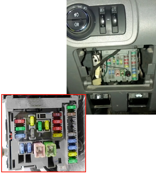
In the car, the fuse and relay box is located in the lower part of the dashboard, on the driver’s side, behind the glove box.
Photo for example
Type 1
Diagram

Assignment
| 1 | 10A HVAC system automatic mode |
| 2 | 30A Bodywork control unit (HVAC system, ventilation and air conditioning) |
| 3 | 15A Bodywork control unit (5) – brake lights |
| 4 | 20A Plug socket |
| 5 | 2A Airbag contact disc in steering wheel |
| 6 | 30A Power windows |
| 7 | 20A Plug socket |
| 8 | 15A Bodywork control unit (2) – dipped beam left |
| 9 | 15A Bodywork control unit (4) – dipped beam right |
| 10 | 30A Bodywork control unit (8) |
| 11 | 40A Switch-off delay |
| 12 | — |
| 13 | — |
| 14 | 7.5A Diagnostic ODB |
| 15 | 10A Airbag control unit |
| 16 | 10A Instrument cluster |
| 17 | 20A Radio |
| 18 | 30A HVAC fan |
| 19 | 5A Exterior mirrors |
| 20 | – |
| 21 | 10A HVAC control unit |
| 22 | 2A Ignition switch |
| 23 | 15A Bodywork control unit (5) |
| 24 | 15A Bodywork control unit (3) |
| 25 | 20A Power window switch |
| 26 | 30A Power seat adjustment |
Fuses 4 and 7 for 20A are responsible for cigarette lighter operation.
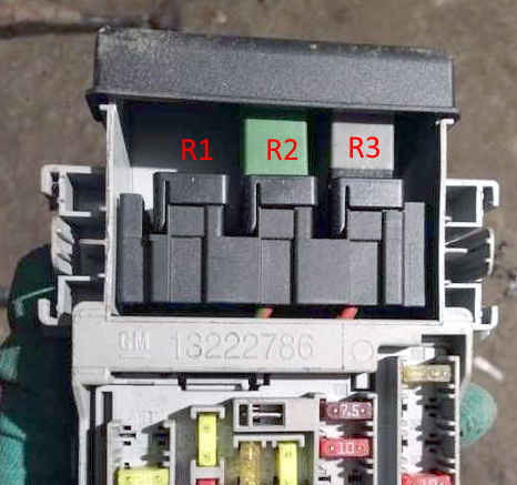
In the upper part of the unit some elements of the auxiliary equipment power relay are installed.
Type 2
Diagram
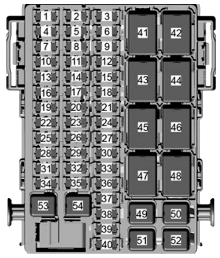
Allocation
| 1 | 20A Body Control Module (6) |
| 3 | 20A Cigarette Lighter (if available) |
| 6 | 20A Front and Rear Power Outlets (if available) |
| 7 | 30A Body Control Module (8) |
| 10 | 20A Radio (if available) |
| 11 | 2A Ignition Switch |
| 12 | 15A Side Blind Zone (SBZ) (If available) |
| 13 | 15A Body Control Module (3) |
| 14 | 10A Front A/C Control Module |
| 15 | 15A Seat Fleated (If available) |
| 16 | 15A Body Control Module (1) |
| 17 | 30A Front Door Power Window Switch |
| 18 | 10A Rear A/C Blower |
| 19 | 30A Rear Door Power Window Switch (if available) |
| 20 | 15A Body Control Module (4) |
| 21 | 10A Spare |
| 22 | 30A Power Seat (if available) |
| 25 | 10A Sensing and Diagnose Module (SDM) |
| 26 | 15A Body Control Module (2) |
| 27 | 2A Clock Spring |
| 28 | 7,5A Data Link Connector (DLC) |
| 30 | 10A Tailgate Lock |
| 31 | 10A Instrument Panel Cluster (IPC), Displays – Radio (Instrument Panel), USB |
| 33 | 10A Central Gateway Module (CGM) – Cyber Security |
| 34 | 30A Front A/C Blower |
| 35 | 30A Rear A/C Blower |
| 37 | 10A Front Collision Alert (FCA) / Rain Sensor |
| 39 | 10A Rear View Mirrors |
| 53 | 40A BUS-C (fuses: F12, F30, F33, F37, F39, F40) |
| 54 | 40A Accessory (12V) |
| Relays | |
| RLY43 | Rear A/C Blower |
| RLY45 | C-Enable |
| RLY46 | RAP and Accessory (12V) |
| RLY47 | RAP and Accessory (12V) |
| RLY48 | Run relay |
If you have anything to add, please write in the comments.