The 5th generation Chevrolet Malibu was produced in 1997 1998 1999 2000 2001 2002 2003. During this time, the model received a facelift. In our publication you can find a description of fuses and relays Chevrolet Malibu 5 with fuse box diagrams, their locations and photo examples of performance. Let’s highlight the cigarette lighter fuse.

The description of the fuses may differ from the one shown and depend on the year of manufacture and the equipment level of your car.
Contents
Passenger compartment
Driver’s side fuse box
In the left end of the dashboard behind the protective cover is the first block with fuses and relays.

Check the assignment of the elements with your diagrams on the back of the protective cover.

Diagram

Assignment
| 1 | 25A Wipers, Multifunction Switch |
| 2 | 10A Trunk Release, Remote Keyless Entry |
| 3 | 10A Turn Sigals |
| 4 | 10A Power Mirrors |
| 5 | 10A Air Bag (Sensing & Diagnostic Module (SDM)) |
| 6 | 10A Body Control Module (BCM) |
| 7 | 10A Powertrain Control Module (PCM) |
| 8 | 15A Power Door Lock |
| 9 | 10A Instrument Panel Cluster, Body Control Module |
| 10 | 15A Stop Lamps |
| 11 | 10A Hazard Lamps |
| 12 | 10A Climate Control, Cluster, Data Link Connector |
| 13 | 10A Radio |
| Relay | |
| R1 | Trunk Release |
| R2 | Power Door Lock (Unlock) |
| R3 | Power Door Lock (Lock) |
| R4 | Driver Door Unlock |
| Circuit Breaker | |
| CB1 | Power Seat |
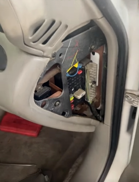
Passenger side fuse box
In the right end of the dashboard behind the protective cover is the second with fuses and relays.
Diagram
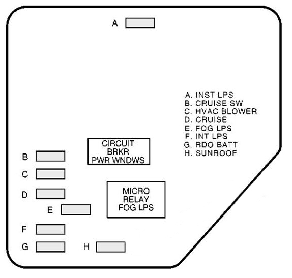
Designation
| A | Instrument Panel Lights, Brightness Control (Dimmer) |
| B | Cruise Control Switches |
| C | Climate Control System |
| D | Cruise Control |
| E | Fog Lamps |
| F | Interior Lamps, Body Function Control Module |
| G | Radio |
| H | Sunroof |
| CIRCUIT BRKR PWR WNDWS | Power Windows |
| MICRO RELAY FOG LPS | Fog Lamps |
Engine compartment
Under the hood, the main fuse and relay box is located on the front left, near the battery.

Diagram

Allocation
| 1 | 30A Ignition Switch |
| 2 | 30A Passenger Compartment Fuse Box (Right (Fuse: “1”, “5”, “6”)) |
| 40A Passenger Compartment Fuse Box (Left (Fuse: “2”, “4”, “8”, “CB1”) | |
| 3 | 30A Passenger Compartment Fuse Box (Left (Fuse: “6”, “10”, “11”, “12”) |
| 4 | 50A ABS |
| 30A Passenger Compartment Fuse Box (Right (Fuse: “1”, “5”, “6”)) | |
| 5 | 40A Ignition Switch |
| 6 | 30A Air Pump |
| 7 | 40A Passenger Compartment Fuse Box (Left (Fuse: “2”, “4”, “8”, “CB1”) |
| 40A ABS | |
| 8 | 30A Cooling Fan No.1 (Left) |
| 23 | – |
| 24 | – |
| 25 | – |
| 26 | – |
| 27 | – |
| 28 | – |
| 29 | – |
| 30 | – |
| 31 | – |
| 32 | – |
| 33 | 30A Rear Window Defogger |
| 34 | 20A Cigar Lighter, Accessory Power Outlets |
| 35 | 10A Generator |
| 10A ABS | |
| 36 | 15A ABS |
| 37 | 10A Air Conditioning Compressor, Body Control Module (BCM) |
| 38 | 10A Automatic Transaxle |
| 39 | 10A Powertrain Control Module (PCM), Ignition |
| 40 | 10A ABS, ABS Relay |
| 41 | 10A Ignition Control Module |
| 42 | 10A Back-Up Lamps, Automatic Transaxle Shift Lock Control System |
| 43 | 15A Horn |
| 44 | 10A Powertrain Control Module (PCM), Mass Air Flow (MAF) Sensor |
| 45 | 15A Parking Lamps |
| 46 | 10A Climate Control System, Air Temperature Actuator, Daytime Running Lamps Relay, Rear Window Defogger Relay |
| 47 | 10A Evaporative Emission (EVAP) Canister Purge Valve, Evaporative Emission (EVAP) Canister Vent Solenoid, Powertrain Control Module (PCM), Heated Oxygen Sensors |
| 48 | 15A Fuel Pump Relay, Fuel Injectors |
| 49 | 10A Generator |
| 50 | 15A Right Headlamp |
| 51 | 15A Left Headlamp, Automatic Lamp Control Relay |
| 52 | 15A Cooling Fan No.2 (Right) |
| 53 | 30A Blower Motor Relay |
| 54 | – |
| 55 | 15A Cooling Fan No.2 (Right) |
| 56 | Fuse Puller |
| 57 | Tach Test Point for Diagnostic Testing |
| Relay | |
| 9 | Rear Window Defogger |
| 10 | – |
| 11 | ABS |
| 12 | Cooling Fan No.1 |
| 13 | Blower Motor |
| 14 | Cooling Fan No.2 |
| 15 | Cooling Fan |
| 16 | Air Conditioning Compressor |
| 17 | – |
| 18 | Fuel Pump |
| 19 | Automatic Lamp Control |
| 20 | Automatic Lamp Control |
| 21 | Horn |
| 22 | Daytime Running Lamps (DRL) |
| Circuit Breaker | |
| CB1 | Power Windows |
On our channel we have also prepared a video on this article, watch and subscribe.
If you have any questions, ask them in the comments.