The sixth generation of the BMW 5 series is the F10. Years of issue f10: 2010, 2011, 2012, 2013, 2014, 2015, 2016 and 2017. During this time, the series has undergone one restyling. This BMW was produced in several body styles: Touring – F11, sedan – F10 and liftback – F07. We provide general information about the Bmw f10 fuses and relay boxes with their descriptions and box diagrams.

The purpose of fuses and relays may differ from those presented and depend on the year of manufacture and the level of electrical equipment of your car.
Contents
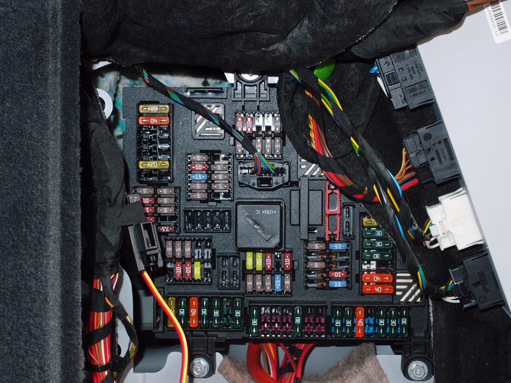
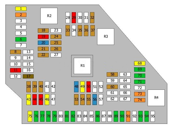
Passenger compartment
Fuse and relay box
As in previous generations of the five, it is located in the glove box (glove compartment). To access, simply open the protective cover.

Diagram
Relays for signal, fog lamps, wipers and other items are marked with squares.
Assignment
| 1 | 10A Footwell control unit |
| 2 | 5A Dynamic Stability Control (DSC) |
| Door control unit | |
| 3 | 5A Central Control Gateway |
| Diagnostic connector | |
| 4 | 5A Control unit |
| 5 | |
| 6 | |
| 7 | 30A Junction Box |
| 8 | 30A Junction Box |
| 9 | 30A Junction Box |
| 10 | 10A Instrument cluster |
| 11 | 7.5A Heating and air conditioning control unit |
| 12 | 5A Glove box light |
| 13 | 5A Steering column switches |
| Switch | |
| Driver assistance system | |
| 14 | 15A Junction box |
| 15 | 20A Junction box |
| 16 | 40A Footwell control unit |
| 17 | 30A Footwell control unit |
| 18 | 30A Footwell control unit |
| 19 | 20A Trailer control unit |
| 20 | |
| 21 | |
| 22 | 30A Pressure control valve |
| Fuel metering solenoid | |
| Camshaft sensor | |
| Boost pressure regulator solenoid | |
| Mass flow meter | |
| Turbo control solenoid | |
| Compressor bypass | |
| 23 | 5A Telematics |
| 24 | 10A Steering column switches |
| 25 | 5A Head-Head Display Control Unit |
| 26 | 5A Instrument cluster |
| 27 | 5A Eject box |
| 28 | 5A Video system |
| 29 | 5A Rear control unit |
| Touchbox control device | |
| 30 | |
| 31 | 5A Rear climate control unit |
| or | |
| Heated rear seat switch | |
| 32 | 7.5A Driver’s seat adjustment switch |
| Door switch control unit | |
| Front passenger seat adjustment switch | |
| Exterior mirror | |
| or | |
| Hatch module | |
| Back light | |
| 33 | 5A Seat belt pretensioner control unit |
| Heating control unit | |
| Tank vent valve | |
| Fuel tank shut-off valve | |
| or | |
| Seat belt pretensioner control unit | |
| Heating control unit | |
| 34 | 5A Chassis Integration Module |
| 35 | 15A DDE main relay |
| 36 | 30A Headlight washer pump |
| 37 | 30A Vertical dynamics control |
| 38 | 40A Vehicle access control unit |
| 39 | 40A Power steering control unit |
| 40 | 30A Dynamic Stability Control (DSC) |
| 41 | |
| 42 | Electro-hydraulic solenoids for engine mounting |
| EGR Cooling Bypass Valve | |
| Oil quality sensor | |
| Oxygen sensor behind the catalytic converter | |
| Oxygen sensor before catalytic converter | |
| Mass flow meter | |
| Compressor bypass | |
| Oil level sensor | |
| Damper control solenoid | |
| 43 | 5A Electromechanical power steering |
| or | |
| Throttle Position Valve | |
| Electromechanical power steering | |
| 44 | 5A Automatic air conditioning |
| Camera control unit | |
| 45 | 5A Vertical Dynamics Control |
| Power steering control unit | |
| 46 | 5A Radiator damper control unit |
| Cruise control | |
| 47 | 20A Exhaust gas recirculation coolant pump |
| Exhaust Gas Recirculation Solenoid | |
| or not used | |
| 48 | 5A Electrochromic rear view mirror |
| Engine crankcase heater | |
| 49 | |
| 50 | |
| 51 | 30A Wiper Module |
| 52 | 30A Driver’s seat control unit |
| or | |
| Driver’s seat adjustment switch | |
| 53 | 30A Passenger seat control unit |
| or | |
| Front passenger seat adjustment switch | |
| 54 | 20A Front and rear 12V sockets, cigarette lighter |
| 55 | 20A Rear wiper |
| 56 | 5A Vehicle access control unit |
| 57 | |
| 58 | 5A Noise filter |
| Hatch module | |
| 59 | 10A Intercooler pump |
| 60 | 5A Parking brake switch |
| 61 | 20A Sunroof 20A |
| 62 | 15A Signal |
| 63 | 10A Automatic Transmission |
| 64 | 7.5A Selector Switch |
| 65 | 15A Additional 12V socket |
| Or | |
| Auxiliary heating system | |
| (20A is also used) | |
| 66 | 7.5A Hatch |
| or | |
| Door switch control unit | |
| Exterior mirror | |
| 67 | 10A Seat adjustment switch |
| or | |
| Driver’s seat adjustment switch | |
| Front passenger seat adjustment switch | |
| Valve block, lumbar support | |
| 68 | 40A Fan |
| 69 | 50A Dynamic Stability Control (DSC) |
| 70 | 60A Cooling fan cut-out relay |
| 71 | 50A Fuel filter heater |
The following fuses are responsible for the cigarette lighter: 54, 65, 108, 147, 176 . Some of them are located in the luggage compartment.
Separately, below the fuse and relay box, there is a cooling fan shut-off relay
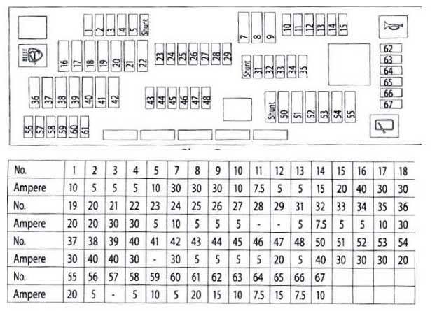
Luggage compartment
Fuse and relay box
To access, open the cover on the right side trim.
Check the purpose with your fusecard located in this block or other technical documentation.
Table with description from fusecard
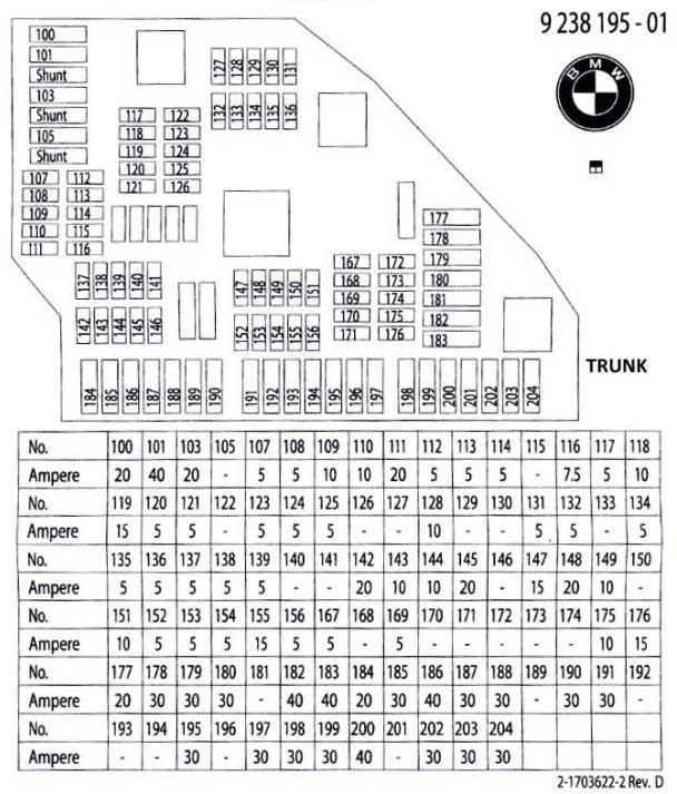

Diagram
Allocation
| 1 | 20A Trailer control unit |
| 2 | 40A Footwell control unit |
| 3 | |
| 4 | |
| 5 | |
| 6 | 30A Hi-Fi amplifier |
| or | |
| Headset connection module | |
| 7 | |
| 8 | 5A Charging control |
| or | |
| Dynamic Stability Control (DSC) | |
| 9 | |
| 10 | |
| 11 | 10A Automatic door |
| 12 | |
| 13 | |
| 14 | |
| 15 | |
| 16 | |
| 17 | 7.5A Rear information display |
| 18 | 5A Telematics |
| USB | |
| 19 | 10A Information display |
| Rear infotainment control unit | |
| 20 | 15A Headset Connection Module |
| Audio system | |
| 21 | 5A Hi-Fi amplifier |
| DVD | |
| 22 | 5A Infotainment control unit |
| Fan | |
| Video system | |
| or | |
| Infotainment control unit | |
| Fan | |
| 23 | |
| 24 | 5A Camera control unit |
| 25 | 5A Night vision system control unit |
| 26 | 5A Video system |
| 27 | |
| 28 | |
| 29 | 10A Damper control solenoid |
| 30 | |
| 31 | |
| 32 | 5A Lane Detection Warning |
| 33 | 5A Additional heater |
| Retractable roof control unit | |
| or | |
| Additional heater | |
| Right high beam headlight | |
| 34 | |
| 35 | 5A Rear axle camber sensor |
| Parking assistance | |
| or | |
| Rear axle camber sensor | |
| Servotronic | |
| 36 | 5A Electrical changeover valve, outlet damper |
| 37 | 5A DC-DC converter |
| Retractable roof control unit | |
| 38 | 5A Cooling fan cut-off relay |
| 39 | 5A Transfer case |
| 40 | 5A Fuel tank leak diagnosis |
| Tire pressure monitoring | |
| 41 | |
| 42 | |
| 43 | 20A Auxiliary heating system |
| 44 | 10A Automatic door |
| 45 | 10A Automatic door |
| 46 | 20A Termination Connector |
| 47 | |
| 48 | 15/20A Additional 12V socket |
| 49 | 20A Convertible roof control unit |
| or | |
| Trailer towing module | |
| 50 | 10A Automatic door |
| 51 | |
| 52 | |
| 53 | 5A Ride Height Control |
| 54 | 5A Trunk lid remote control |
| Rear door switch | |
| 55 | 5A Trunk light(s) |
| 56 | 15A Rear door/trunk lock |
| 57 | |
| 58 | 5A Parking brake control unit |
| 59 | |
| 60 | 5A Alarm |
| or | |
| Emergency system | |
| Vacuum leak detection | |
| 61 | |
| 62 | |
| 63 | |
| 64 | |
| 65 | |
| 66 | |
| 67 | |
| 68 | 20A Heater fan |
| 69 | 30A Transfer case |
| 70 | 30A Parking brake control unit |
| 71 | 30A Parking brake control unit |
| 72 | |
| 73 | 40A Compressor clutch relay |
| or | |
| Soft top | |
| 74 | 40A Remote control for trunk lid |
| 75 | 20A Fuel pump control |
| 76 | 30A Hi-Fi amplifier |
| or not used | |
| 77 | 30A DC-DC converter |
| 78 | 30A Heated rear seat control unit |
| or | |
| Rear seat control unit | |
| 79 | 30A Heated rear seat control unit |
| or | |
| Rear seat control unit | |
| 80 | |
| 81 | 30A Driver seat heating control unit |
| 82 | 30A Passenger seat heating control unit |
| 83 | |
| 84 | |
| 85 | |
| 86 | 30A Auxiliary heater |
| 87 | |
| 88 | |
| 89 | 30A Seat belt pretensioner control unit |
| or not used | |
| 90 | 30A Seat belt pretensioner control unit |
| or not used | |
| 91 | 40A Hi-Fi amplifier |
| 92 | |
| 93 | 30A Auxiliary heater |
| 94 | 30A Heated rear window |
| 95 | |
| R1 | Terminal 30 relay |
| R2 | Terminal 30 relay |
| R3 | Terminal 15 relay |
| R4 | Heated rear window relay |
Fuse box
An additional fuse box can be installed next to the main fuse and relay box if there is an additional battery in the car.
Scheme

Appointment
- Additional battery control unit 5A
- Reserve
- Additional battery control unit 20A
- Sound control unit 5/2A
- Charging connector 10A
- Sound control unit 20A
- Reserve 5A
- Reserve 5A
- Additional battery control unit 5A
- Reserve
- Charging connector 10A
- Reserve
- Reserve 5A
- Switches 5A
- Reserve
- Additional battery control unit 5A
- Reserve 10A
- Additional battery control unit 10A
- Additional battery control unit 5A
- Additional battery control unit 5A
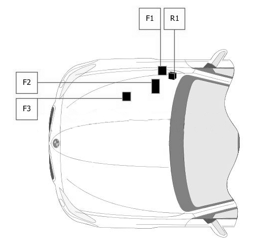
Relay box
Diagram

Decoding
- R1 – alarm
- R2 – rear electric windows
- R3 – shutdowns
- R4 – rear electric windows
- R5 – compressor clutch
- F1 – 100.0 A – fuse box No. 2 in the luggage compartment
Power fuse box
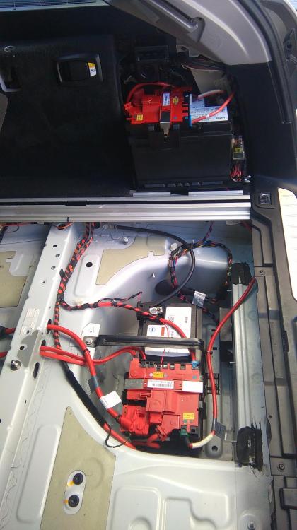
On the positive terminal of the battery (if there is an additional battery, there are also controls nearby) there are main high-power fuses and some relays:
| 1 | 100A Cooling Fan Cut-Off Relay |
| 2 | 100A DDE main relay |
| 3 | 100/125A Electromechanical power steering |
| Trip relay | |
| Fuse box No. 2 in luggage compartment | |
| 4 | Reserve |
| 5 | Reserve |
| 6 | 50A Hi-Fi amplifier |
| 7 | 60A Rear axle camber sensor |
| 8 | 100A Fuse Box No. 1 in Luggage Compartment |
| 9 | 250A Junction Box |
| 10 | 100/150A Fuse Box No. 1 in Luggage Compartment |
Engine compartment
Fuse and relay box
Diagram
Assignment
| 1 | 5A Electromechanical power steering |
| 2 | 30A Distributor |
| Engine electronics | |
| or | |
| Engine electronics | |
| 3 | 125A Electromechanical power steering |
| or | |
| Electromechanical power steering | |
| Capacitor | |
| R1 | DDE main relay |
Check out our YouTube video for more on this topic. Don’t forget to subscribe!
And if you have something to add, write in the comments.
I cannot get to fuse #65 in the glove box because that whole row seems to be covered by the big black square thing shown on the diagrams as a big empty square. How does that thing pull out for me to get access to the row that contains #65. Thanks for any assistance.
Reading up on this it seems as though the UK cars fuses in the glove box are installed upside down.
I cant seem to find a fuse listing for the front heated screen . No where do the lists show anything for ” front heated windscreeen ” etc. But I see one heated screen symbol alongside 203 and 204 30a fuses. Does this mean that 203 and 204 are the rear and front heated elements? Cheers
Hello,
Do you know the fuse for the rollo automatic sunscreen for the back window of the F10 2010?
Greetings
Helo do know where the laod sheding relay is on bmw f10 with n20 engine 2010