The fifth generation of the 7 Series BMW is designated by the body index – F01 / F02 (extended version), a separate series was designated as Alpina B7. This car was produced in 2008, 2009, 2010, 2011, 2012, 2013, 2014 and 2015. This material will discuss the power supply circuit, a detailed description of the fuses and relays of the BMW F01 F02 with their diagrams and photo examples of execution. Let’s highlight the fuses responsible for the cigarette lighter.

Depending on the configuration and year of manufacture, your assignment of fuses and relays may differ from the information provided.
Contents
Power system overview
The general scheme looks like this.

- Generator;
- Battery positive output;
- Power distribution box in the engine compartment;
- Control electronics compartment in the engine compartment;
- Front fuse holder behind the glove compartment;
- Rear fuse holder on the right side of the luggage compartment;
- Accumulator battery;
- Starter.
Passenger compartment
Inside the car, the main unit with fuses and relays is located in the glove compartment (or what I call the glove box).
It should also contain up-to-date information on the location of the fuses for your model in the form of a sheet of paper (fusecard).
- Front fuse holder;
- Junction box electronics.
It looks like this.

Diagram


Assignment
| 1 | 10A Footwell control unit |
| 2 | 5A Dynamic Stability Control (DSC) |
| Door control unit | |
| 3 | 5A Central Control Gateway |
| Diagnostic connector | |
| 4 | 5A Control unit |
| 5 | |
| 6 | |
| 7 | 30A Junction Box |
| 8 | 30A Junction Box |
| 9 | 30A Junction Box |
| 10 | 10A Instrument cluster |
| 11 | 7.5A Heating and air conditioning control unit |
| 12 | 5A Glove box light |
| 13 | 5A Steering column switches |
| Switch | |
| Driver assistance system | |
| 14 | 15A Junction box |
| 15 | 20A Junction box |
| 16 | 40A Footwell control unit |
| 17 | 30A Footwell control unit |
| 18 | 30A Footwell control unit |
| 19 | 20A Trailer control unit |
| 20 | |
| 21 | |
| 22 | 30A Pressure control valve |
| Fuel metering solenoid | |
| Camshaft sensor | |
| Boost pressure regulator solenoid | |
| Mass flow meter | |
| Turbo control solenoid | |
| Compressor bypass | |
| 23 | 5A Telematics |
| 24 | 10A Steering column switches |
| 25 | 5A Head-Head Display Control Unit |
| 26 | 5A Instrument cluster |
| 27 | 5A Eject box |
| 28 | 5A Video system |
| 29 | 5A Rear control unit |
| Touchbox control device | |
| 30 | |
| 31 | 5A Rear climate control unit |
| or | |
| Heated rear seat switch | |
| 32 | 7.5A Driver’s seat adjustment switch |
| Door switch control unit | |
| Front passenger seat adjustment switch | |
| Exterior mirror | |
| or | |
| Hatch module | |
| Back light | |
| 33 | 5A Seat belt pretensioner control unit |
| Heating control unit | |
| Tank vent valve | |
| Fuel tank shut-off valve | |
| or | |
| Seat belt pretensioner control unit | |
| Heating control unit | |
| 34 | 5A Chassis Integration Module |
| 35 | 15A DDE main relay |
| 36 | 30A Headlight washer pump |
| 37 | 30A Vertical dynamics control |
| 38 | 40A Vehicle access control unit |
| 39 | 40A Power steering control unit |
| 40 | 30A Dynamic Stability Control (DSC) |
| 41 | |
| 42 | Electro-hydraulic solenoids for engine mounting |
| EGR Cooling Bypass Valve | |
| Oil quality sensor | |
| Oxygen sensor behind the catalytic converter | |
| Oxygen sensor before catalytic converter | |
| Mass flow meter | |
| Compressor bypass | |
| Oil level sensor | |
| Damper control solenoid | |
| 43 | 5A Electromechanical power steering |
| or | |
| Throttle Position Valve | |
| Electromechanical power steering | |
| 44 | 5A Automatic air conditioning |
| Camera control unit | |
| 45 | 5A Vertical Dynamics Control |
| Power steering control unit | |
| 46 | 5A Radiator damper control unit |
| Cruise control | |
| 47 | 20A Exhaust gas recirculation coolant pump |
| Exhaust Gas Recirculation Solenoid | |
| or not used | |
| 48 | 5A Electrochromic rear view mirror |
| Engine crankcase heater | |
| 49 | |
| 50 | |
| 51 | 30A Wiper Module |
| 52 | 30A Driver’s seat control unit |
| or | |
| Driver’s seat adjustment switch | |
| 53 | 30A Passenger seat control unit |
| or | |
| Front passenger seat adjustment switch | |
| 54 | 20A Front and rear 12V sockets, cigarette lighter |
| 55 | 20A Rear wiper |
| 56 | 5A Vehicle access control unit |
| 57 | |
| 58 | 5A Noise filter |
| Hatch module | |
| 59 | 10A Intercooler pump |
| 60 | 5A Parking brake switch |
| 61 | 20A Sunroof 20A |
| 62 | 15A Signal |
| 63 | 10A Automatic Transmission |
| 64 | 7.5A Selector Switch |
| 65 | 15A Additional 12V socket |
| Or | |
| Auxiliary heating system | |
| (20A is also used) | |
| 66 | 7.5A Hatch |
| or | |
| Door switch control unit | |
| Exterior mirror | |
| 67 | 10A Seat adjustment switch |
| or | |
| Driver’s seat adjustment switch | |
| Front passenger seat adjustment switch | |
| Valve block, lumbar support | |
| 68 | 40A Fan |
| 69 | 50A Dynamic Stability Control (DSC) |
| 70 | 60A Cooling fan cut-out relay |
| 71 | 50A Fuel filter heater |
Separately, we note: fuses 54, 65, 147, 176 are responsible for the cigarette lighter. Half of them are in the luggage compartment.
The relays are marked with squares: signal relay, windshield wiper relay, and others.
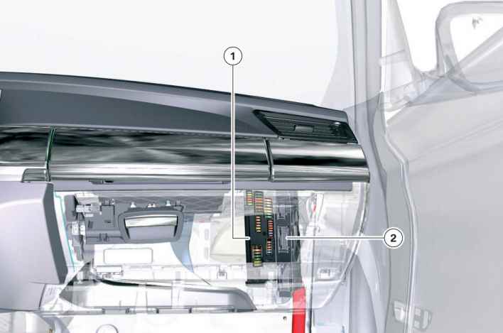
Luggage compartment
Fuse and relay box
Due to the large number of consumers and control units, an additional fuse holder is installed in the luggage compartment F01 / F02. It is located on the right side under the skin.

Along with the fuses, some more relays are inserted into it or soldered onto the board.

- Relay terminal 30B (inserted);
- Contact 30F relay (soldered);
- Contact 15N relay (soldered);
- Relay for heating the rear window (soldered).
Designation

Check the purpose of the elements with your diagram or other technical documentation.
Table with decoding of elements

Fuse box
An additional fuse box can be installed next to the main fuse and relay box if there is an additional battery in the car.
Scheme

Appointment
- Additional battery control unit 5A
- Reserve
- Additional battery control unit 20A
- Sound control unit 5/2A
- Charging connector 10A
- Sound control unit 20A
- Reserve 5A
- Reserve 5A
- Additional battery control unit 5A
- Reserve
- Charging connector 10A
- Reserve
- Reserve 5A
- Switches 5A
- Reserve
- Additional battery control unit 5A
- Reserve 10A
- Additional battery control unit 10A
- Additional battery control unit 5A
- Additional battery control unit 5A
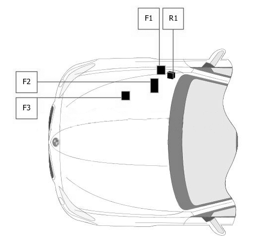
Relay box
Diagram

Decoding
- R1 – alarm
- R2 – rear electric windows
- R3 – shutdowns
- R4 – rear electric windows
- R5 – compressor clutch
- F1 – 100.0 A – fuse box No. 2 in the luggage compartment
Power fuse box
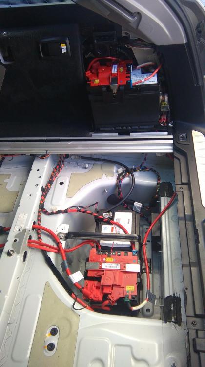
On the positive terminal of the battery (if there is an additional battery, there are also controls nearby) there are main high-power fuses and some relays:
| 1 | 100A Cooling Fan Cut-Off Relay |
| 2 | 100A DDE main relay |
| 3 | 100/125A Electromechanical power steering |
| Trip relay | |
| Fuse box No. 2 in luggage compartment | |
| 4 | Reserve |
| 5 | Reserve |
| 6 | 50A Hi-Fi amplifier |
| 7 | 60A Rear axle camber sensor |
| 8 | 100A Fuse Box No. 1 in Luggage Compartment |
| 9 | 250A Junction Box |
| 10 | 100/150A Fuse Box No. 1 in Luggage Compartment |
Engine compartment
Diagram
Assignment
| 1 | 5A Electromechanical power steering |
| 2 | 30A Distributor |
| Engine electronics | |
| or | |
| Engine electronics | |
| 3 | 125A Electromechanical power steering |
| or | |
| Electromechanical power steering | |
| Capacitor | |
| R1 | DDE main relay |
Check out our YouTube video for more on this topic. Don’t forget to subscribe!
If you have something to add, write in the comments.
Hello, which is the fuse for aircon fan in the boot.
where is fuse 68 located? It is shown on this helpful guide as a 40a fan, but neither of the diagrams have a fuse location 68 or even 69,70 or 71.
Hol található a riasztó sziréna és az ehhez tartozó biztosíték ?