The first-generation Audi Q2 subcompact crossover was produced in 2017, 2018, 2019, 2020, 2021, 2022, 2023, 2024, 2025, and 2026. During this time, the model was updated. In this article, you will find a description of the Audi Q2 fuses and relays, including fuse diagrams, their locations, and example photos. We also will highlight the fuse responsible for the cigarette lighter.

The purpose of the fuses and relays may differ from the one shown and depends on the year of manufacture, configuration and country of delivery. In case of difficulty, contact your nearest dealer.
Passenger compartment
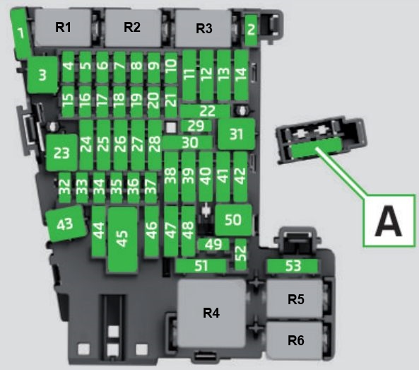
Fuse box is located at the bottom of the instrument panel, on the driver’s side. You need to remove the glove box to access.

Photo

Diagram
Assignment
| F1 | AdBlue engine components |
| F2 | Seat adjuster |
| F4 | Infotainment control console |
| F5 | Gateway |
| F6 | Selector lever (for automatic gearbox) |
| F7 | Air conditioner/ heater console, relay coil for rear window heating |
| F8 | Switch for electro-mechanical parking brake, light switch, rain/ light sensor, interior lighting, anti-theft alarm system, diagnostic connector, emergency call system |
| F9 | Steering column switch module |
| F10 | Infotainment/ head-up display |
| F11 | Belt tensioners (driver’s side) |
| F12 | Infotainment components |
| F13 | Control unit for suspension control |
| F14 | Blower (heating system/air conditioner) |
| F15 | Electric steering column lock |
| F16 | Infotainment components |
| F17 | Instrument cluster |
| F18 | Reversing camera |
| F19 | Control unit for convenience access, park assist |
| F20 | AdBlue engine components |
| F22 | Power-operated boot lid |
| F23 | Control unit for vehicle electrical system (right side) |
| F24 | Panorama sun roof |
| F25 | Front/ rear door control unit, front/rear window switches |
| F26 | Seat heating |
| F27 | Sound amplifier |
| F29 | Interior lights |
| F31 | Control unit for vehicle electrical system (left side) |
| F32 | Control unit for camera, radar sensor, park assist |
| F33 | Airbag |
| F34 | Button lighting for hold assist, interior sound, reversing light switch, temperature sensor, coil for electrical socket relay, button for hold assist |
| F35 | Function lighting (halogen), headlight range control, air quality sensor, automatic anti-dazzle mirrors, diagnostic connector, centre console power supply |
| F36 | Right headlight (LED) |
| F37 | Left headlight (LED) |
| F39 | Front/ rear door control unit, front/rear window switches |
| F40 | Cigarette lighter, electrical sockets |
| F41 | Belt tensioners (front passenger’s side) |
| F42 | Central locking system, windscreen washer |
| F43 | Interior lights |
| F44 | Four-wheel drive |
| F47 | Rear window wiper |
| F49 | Clutch sensor (relays 1+2) |
| F53 | Rear window heating |
The fuse number 40, 20A, is responsible for the cigarette lighter.
Relay
- R1 – Relay for reducing agent dosing system
- R2 –
- R3 –
- R4 – Voltage supply relay at terminal 15
- R5 – Rear window defroster relay
- R6 – Power socket relay
Engine compartment
The main fuse box under the hood is located on the left side of the engine compartment, next to the battery.
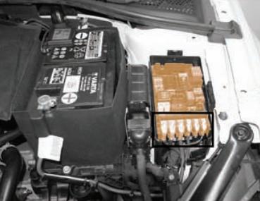
Photo

Diagram

Designation
Fuses
| F1 | Electronic stabilisation control (ESC) |
| F2 | Electronic stabilisation control (ESC) |
| F3 | Engine control unit |
| F4 | Engine components, engine cooling, supplementary heater relay coils (1+4+7), secondary air pump relay |
| F5 | Engine components, tank system (diesel) |
| F6 | Brake light sensor |
| F7 | Engine components, coolant pumps, tank system (petrol) |
| F8 | Lambda probe |
| F9 | Engine components, exhaust flap, control unit for automatic glow period (relay 6) |
| F10 | Fuel control unit, fuel pump |
| F11 | Supplementary heater heating rod 2 |
| F12 | Supplementary heater heating rod 3 |
| F13 | Automatic gearbox |
| F15 | Horn |
| F16 | Ignition coil (relay 8) |
| F17 | Electronic stabilisation control (ESC), engine control unit (relay 5) |
| F18 | Battery monitoring, gateway |
| F19 | Windscreen wipers |
| F20 | Anti-theft alarm system |
| F22 | Terminal 50, diagnostics, engine control unit |
| F23 | Starter |
| F24 | Supplementary heater heating rod 1 |
| F31 | Vacuum pump |
| F33 | Automatic gearbox, gearbox oil pump |
Relays
| R1 | Starter Relay 1 |
| R2 | Starter Relay 2 |
| R3 | Horn Relay |
| R4 | High Heat Output Relay (Diesel) |
| R5 | Main Relay (Gasoline) |
| Power Relay at Terminal 30 (Diesel) | |
| R6 | Automatic Glow Period Control Module (Diesel) |
| R7 | Low Heat Output Relay (Diesel) |
| R8 | Engine Component Power Relay (2.0L Gasoline) |
| R9 | Wiper Motor Relay 1 |
| R10 | Wiper Motor Relay 2 |
| SBJ | 125A Fuses in Fuse Holder C (Instrument Panel): No. 4, 14, 22, 31, 38, 42, 53 |
| Power Relay at Terminal 15 | |
| Socket Relay | |
| SBG | Alternator 400A |
| 508 | Battery |
| SBE | Power Steering Control Module 80A |
| SBK | 80A Fuses in Fuse Holder C (Instrument Panel): No. 1, 3, 15, 30, 43, 46, 50, 52 |
| SBL | Radiator fan 50 A |
Check out our YouTube video for more on this topic. Don’t forget to subscribe!
There is something to add – write in the comments.