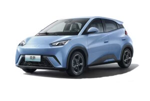
The BYD Seagull has been produced since 2023. It is also known as the Dolphin Mini, Dolphin Surf and Atto 1. During this time, the model has been restyled and updated. In our article, you can find information describing the BYD Seagull’s fuses and relays, along with block diagrams and location information and photo examples. We’ll also show the fuses responsible for the cigarette lighter and USB ports.
The design of the units and the purpose of the elements within them may differ from that shown and depend on the year of manufacture, region of delivery, and the level of electrical equipment in your vehicle.
Passenger compartment
Inside the vehicle, the fuse box is located at the bottom of the dashboard on the driver’s side (left or right side, respectively). To access it, first remove the left black end cover. Next, remove the lower guard.
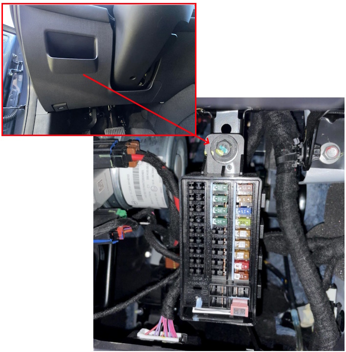
Check the assignment against your diagrams or other technical documentation.
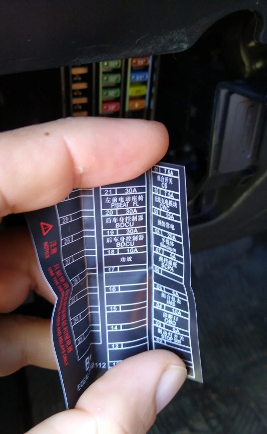
Diagram
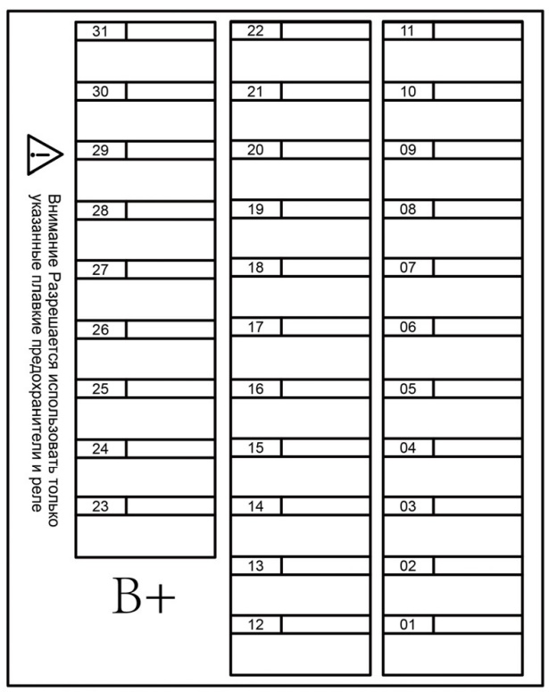
Assignment
| F01 | 30A Universal Controller |
| F02 | 30A Trailer Power Supply |
| F03 | 5A Brake Light Switch |
| F04 | 10A OBD Diagnostic Port |
| F05 | 5A Instrument Cluster |
| F06 | 10A Alcohol Interlock Module |
| F07 | 5A Gearshift Panel |
| F08 | 20A Infotainment System (Head Unit) |
| F09 | 15A External Audio Amplifier |
| F10 | 10A ADAS (Advanced Driver Assistance Systems) |
| F11 | 7.5A Combination Switch (Turn Signal, Wiper, etc.) |
| F12 | 30A Rear Body Control Module (RBCM) |
| F13 | 30A Rear Body Control Module (RBCM) |
| F14 | 10A CCS Communication Module (Combined Charging System) |
| F15 | 20A Front Left Power Window |
| F16 | 20A Front Right Power Window |
| F17 | 20A Rear Left Power Window |
| F18 | 20A Rear Right Power Window |
| F19 | 5A eCall Emergency Communication Module |
| F20 | 7.5A Wireless Charger |
| F21 | 30A Front Left Power Seat (Driver Seat) |
| F22 | 30A Front Right Power Seat (Passenger Seat) |
| F23 | Spare |
| F24 | Spare |
| F25 | Spare |
| F26 | Spare |
| F27 | Spare |
| F28 | Spare |
| F29 | Spare |
| F30 | Spare |
| F31 | Spare |
Engine compartment
Under the hood, the main fuse and relay box is located on the front left.
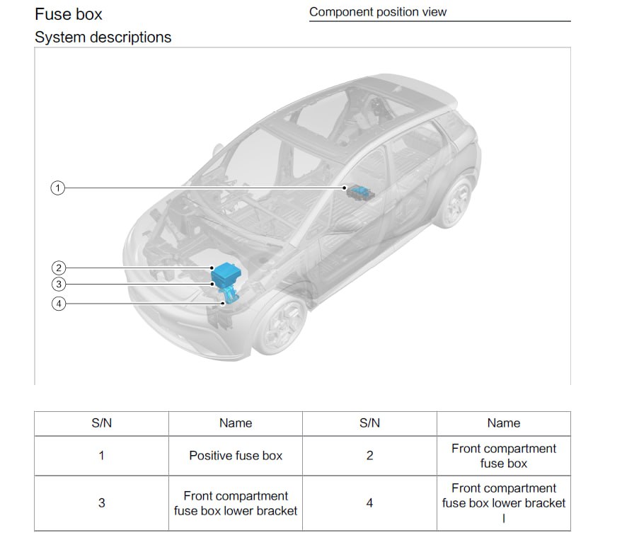
To access, remove the top cover of the unit.

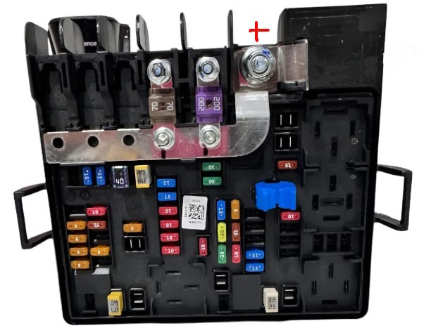
The fuse box itself will look something like this.
Diagram
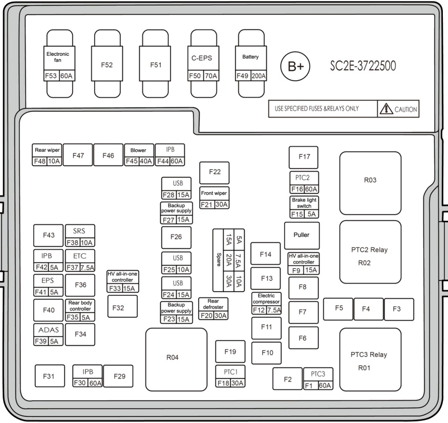
Designation
| F1 | 60A PTC Heater No. 3 |
| F2 | Spare |
| F3 | Spare |
| F4 | Spare |
| F5 | Spare |
| F6 | Spare |
| F7 | Spare |
| F8 | Spare |
| F9 | 15A HV All-in-One Controller |
| F10 | 15A Left Combination Headlight |
| F11 | 15A Right Combination Headlight |
| F12 | 7.5A Electric Compressor |
| F13 | 10A Electric Coolant Pump |
| F14 | 10A Motor Controller |
| F15 | 7.5A Integrated Thermal Management Module |
| F16 | 60A PTC Heater No. 2 |
| F17 | Spare |
| F18 | 30A PTC Heater No. 1 |
| F19 | Spare |
| F20 | 7.5A Right Daytime Running Light (DRL) |
| F21 | 30A Front Wiper |
| F22 | 30A Rear Window Defroster |
| F23 | 15A Auxiliary Power Supply |
| F24 | 15A USB Power Supply |
| F25 | 10A USB Power Supply |
| F26 | Spare |
| F27 | 15A Auxiliary Power Supply |
| F28 | 15A USB Power Supply |
| F29 | Spare |
| F30 | 60A ESC (Electronic Stability Control) |
| F31 | 20A Trailer Power Supply |
| F32 | Spare |
| F33 | 15A HV All-in-One Controller |
| F34 | 15A Heated Steering Wheel |
| F35 | 5A Rear Body Control Module (RBCM) |
| F36 | 5A Instrument Cluster |
| F37 | 7.5A Electronic Throttle Control (ETC) |
| F38 | 10A SRS Airbag System |
| F39 | 5A ADAS (Advanced Driver Assistance Systems) |
| F40 | Spare |
| F41 | 5A EPS (Electric Power Steering) |
| F42 | 5A ESC (Electronic Stability Control) |
| F43 | Spare |
| F44 | 60A ESC (Electronic Stability Control) |
| F45 | 40A HVAC Blower Motor |
| F46 | Spare |
| F47 | Spare |
| F48 | 10A Rear Wiper |
| F49 | 200A Main Battery |
| F50 | 70A C-EPS (Column Electric Power Steering) |
| F51 | Spare |
| F52 | 60A Electric Cooling Fan |
| F53 | Spare |
Fuses 27 and 28, rated at 15A, are responsible for the cigarette lighter and USB port.
- R1 PTC3 Relay — Relay for the 3rd electric PTC heater in the cabin heater
- R2 PTC2 Relay — Relay for the 2nd electric PTC heater in the cabin heater
- R3 FAN LO Relay — Low-speed engine cooling fan relay
- R4 FAN HI Relay — High-speed engine cooling fan relay
If you have anything to add, please write in the comments.