Toyota Land Cruiser 70 is a full-size SUV produced from 1984 to the present day with both petrol and diesel engines in various modifications and changes – LJ73, LJ76, LJ78, RJ73, RJ76 и RJ78. In this post you can find a description of fuses and relays Toyota Land Cruiser 70 with fuse box diagrams, their locations and photo examples of performance. We also highlight the fuse responsible for the cigarette lighter.

The purpose of some elements in the diagrams may differ from the one presented and depends on the year of manufacture, configuration and country of delivery. In case of difficulty, contact your nearest dealer.
Contents
Passenger compartment
Type 1
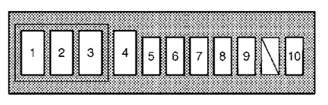
Up to 2009
The fuse box is mounted on the pillar under the instrument panel, on the driver’s side, and is covered with a protective cover.
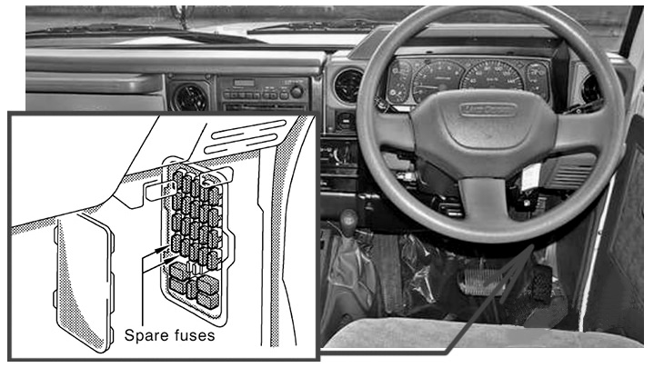
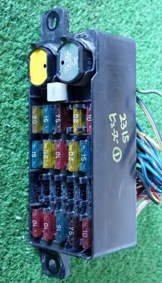
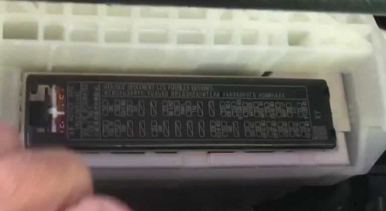
Photo for example
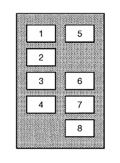
Diagram
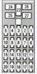
Assignment
| 1 | SPARE — 7.5A |
| 2 | SPARE — 15A |
| 3 | CHARGE / IGN — 7.5A — Gasoline: No circuit / Diesel: Electronically controlled fuel injection pump system |
| 4 | CIG — 15A — Cigarette lighter, clock, radio |
| 5 | EFI / ECD — 15A — Fuel injection system |
| 6 | A.C — 10A — Air conditioning system |
| 7 | TURN — 10A — Turn signal lights |
| 8 | DEFOG — 15A — No circuit |
| 9 | WIPER — 20A — Wipers, washers, back-up lights |
| 10 | ENGINE — 15A — Charging system, gauges, warning system |
| 11 | ST — 30A — Diesel starting system |
| 12 | STOP — 10A — Brake lights |
| 13 | DOME — 10A — Interior light, clock, radio |
| 14 | RADIO — 10A — Diesel: No circuit |
| 15 | ECU-B — 10A — Exhaust gas recirculation system |
| 16 | TAIL — 20A — Tail / parking / plate / panel lights |
| 17 | GLOW — 7.5A — Diesel: No circuit |
| 18 | HAZ-HORN — 15A — Hazard lights, horn |
| 19 | HEAD (LH) — 10A — Left headlight |
| 20 | HEAD (RH) — 10A — Right headlight |
| 21 | IGN / FUEL-HTR — 7.5A / 15A — Fuel injection / Fuel heater |
| 22 | DOOR — 30A — Power door locks |
| 23 | HEATER — 30A — Air conditioning system |
| 24 | POWER — 30A — Power windows |
| 25 | DIFF — 30A — Differential lock / 4WD system |
Fuse number 4, 15A, is responsible for the operation of the cigarette lighter.
Type 2
From 2009
Fuse box 1
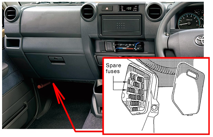
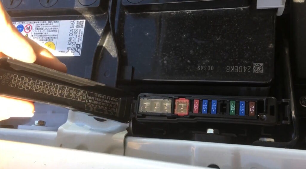
This fuse box is located on the left pillar under the dashboard on the passenger side.
Photo
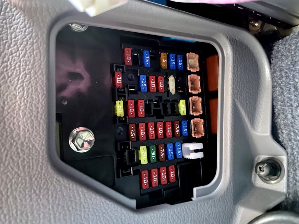
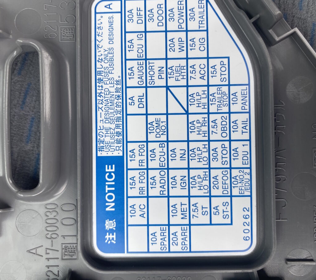
Check the current assignment of the elements with your diagrams on the back of the block cover.
Diagram
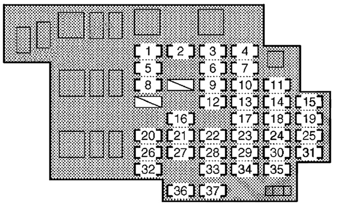
Designation
| 1 | DIFF — 30A — Differential lock system |
| 2 | DOOR — 30A — Power door lock / remote control system |
| 3 | POWER — 30A — Power windows |
| 4 | TRAILER — 30A — Trailer tail / turn lights |
| 5 | ECU IG — 15A — Fuel injection pump, charging, glow system, 4WD, wipers, antenna, ABS |
| 6 | WIP — 20A — Windshield wipers and washer |
| 7 | CIG — 15A — Cigarette lighter |
| 8 | GAUGE — 15A — Back-up lights, A/C, defogger, clock, flashers |
| 9 | FUEL HTR — 15A — Fuel heater |
| 10 | ACC — 7.5A — Clock, audio system, power antenna |
| 11 | STOP — 15A — Fuel injection system, brake lights |
| 12 | DC/DC — 15A — DC/DC converter |
| 13 | H/LP HI LH — 10A — No circuit |
| 14 | TRAILER STOP — 15A — Trailer stop lights |
| 15 | PANEL — 10A — Instrument panel, gauges, audio, A/C |
| 16 | DOME №1 — 10A — Interior light, gauges |
| 17 | H/LP HI RH — 10A — Right high beam headlight |
| 18 | OBD2 — 7.5A — Diagnostic system |
| 19 | TAIL — 10A — Parking / tail / plate lights |
| 20 | FR FOG — 15A — Front fog lights |
| 21 | ECU-B — 10A — Fuel injection system, clock, antenna |
| 22 | INJ — 10A — Fuel injection system |
| 23 | H/LP LO LH — 10A — Left low beam headlight |
| 24 | STOP — 30A — STOP and TRAILER STOP circuits |
| 25 | DOME №2 — 10A — Interior lights |
| 26 | RR FOG — 15A — No circuit |
| 27 | RADIO — 15A — Audio system |
| 28 | IGN — 10A — Fuel injection system, SRS airbag |
| 29 | H/LP LO RH — 10A — Right low beam headlight |
| 30 | DEFOG — 20A — Rear window defogger |
| 31 | EFI №2 — 10A — Fuel injection system |
| 32 | A/C — 10A — Air conditioning system |
| 33 | MET — 10A — Gauges and meters |
| 34 | ST — 7.5A — Starting and glow system |
| 35 | BLACK — 7.5A — No circuit |
| 36 | SPARE — 10A — Spare fuse |
| 37 | SPARE — 20A — Spare fuse |
Fuse number 7, 15A, is responsible for the operation of the cigarette lighter.
Fuse box 2
The next fuse box is installed in newer models under the glove compartment.
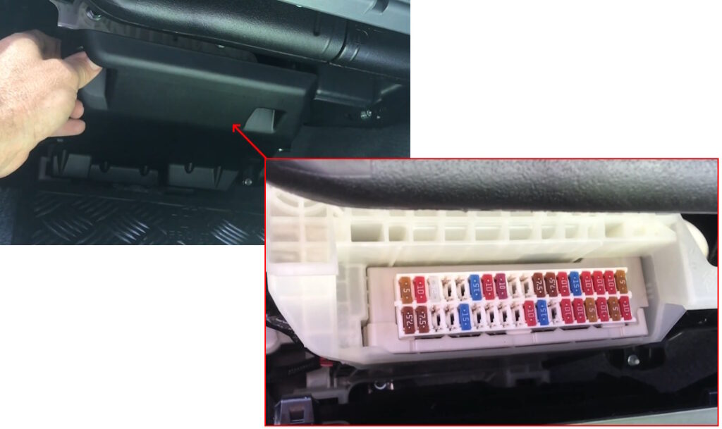
The assignment of the fuses will be indicated on the cover of the unit.
The following fuses may be located here:
- BCM
- AUDIO
- METER
- ROOM LAMP
- AIR BAG
- WASHER
- PWR SOCKET
- BLOWER
- IGN
- ACC
- TAIL
Engine compartment
Under the hood, the fuse boxes are located next to the battery.
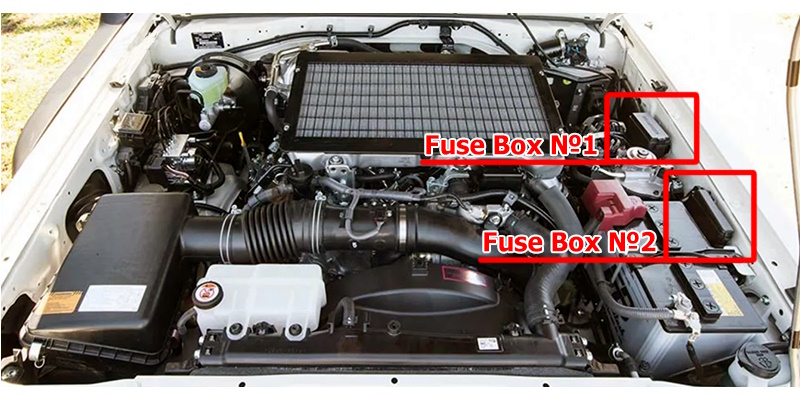
Fuse box 1
Diagram
Allocation
| 1 | HTR — 50A — Air conditioning system |
| 2 | ALT — 140A — Main power supply for multiple fuse circuits |
| 3 | GLOW1 — 80A — Engine glow system |
| 4 | GLOW2 — 80A — Engine glow system |
| 5 | AM1 №2 — 50A — ECU IG, GAUGE, WIP circuits, fog lights |
| 6 | AM1 — 30A — Cigarette lighter, starting system, ST and ACC circuits |
| 7 | AM1 №3 — 50A — Cigarette lighter, ACC circuits |
| 8 | ALT MAIN — 50A — Stop lights, A/C, diagnostics, audio system |
Fuse box 2
Diagram
Decoding
| 1 | MAIN2 / ABS MTR — 50A — Audio, ECU-B, DOME, DOOR circuits / ABS |
| 2 | HEAD — 50A — Left/right low & high beam headlights |
| 3 | MAIN1 — 50A — Tail lights, fog lights, PANEL circuits, trailer, audio |
| 4 | AM2 — 50A — MET, IGN and INJ circuits |
| 5 | HORN — 10A — Horns |
| 6 | EFI MAIN — 15A — Electronically controlled fuel injection system |
| 7 | EFI MAIN2 — 15A — Electronically controlled fuel injection system |
| 8 | TURN&HAZ — 15A — Turn signals, hazard lights, trailer lights |
| 9 | ABS SOL — 30A — ABS system |
| 10 | ALT-S — 7.5A — Charging system |
Check out our YouTube video for more on this topic. Don’t forget to subscribe!