The Volkswagen Crafter is still available in various body styles: minibus, light truck and van. Years of release of the 1st generation: 2006, 2007, 2008, 2009, 2010, 2011, 2012, 2013, 2014, 2015, 2016. During this period, the car was restyled. Since 2017, the second generation of the updated Volkswagen Crafter has been delivered to the markets. In this article you will find a designation of Volkswagen Crafter fuse boxes and relays, diagrams and photographs of the boxes, as well as their location. Let’s highlight the fuse responsible for the cigarette lighter.

Depending on your vehicle equipment level (Standard, HighLine, etc.) and the year of manufacture, different designs of fuse boxes and relays are possible.
Contents
Boxes locations
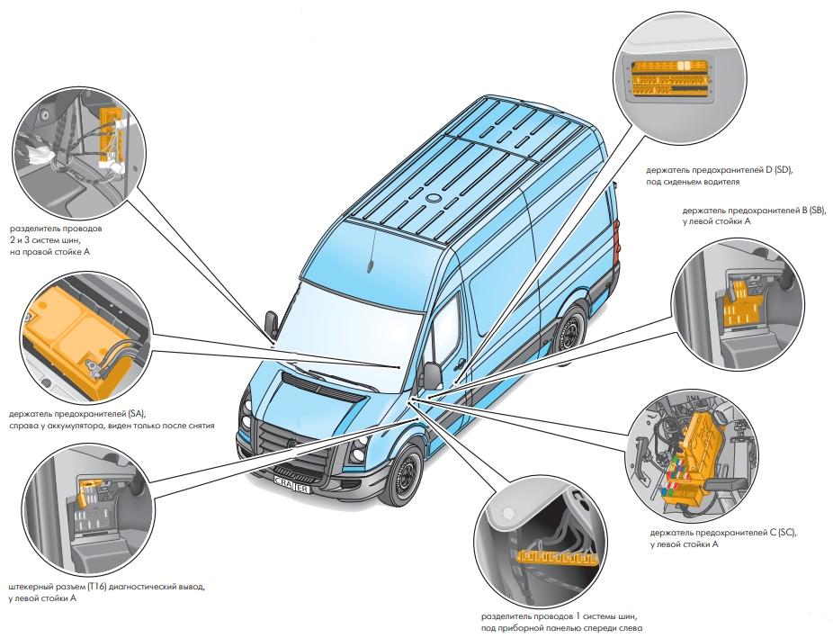
The following blocks are provided in Volkswagen Crafter:
- Power supply fuse, cl. 30 -S190-
- Battery fuse holder A -SA-
- Fuse holder B, left pillar -SB-
- Left-hand fuse and relay box C -SC-
- Fuse and relay holder D under driver’s seat -SD-
- Additional relay under the driver’s seat
Power supply fuse, cl. thirty
Main power supply fuse, cl. 30, located in the wiring harness between the alternator and starter

Battery fuse box
It consists of high power fuse-links.

Diagram

Assignment
| 1 | 80A Glow plug control unit |
| 2 | 40/60 / 80A Radiator fan control unit, Radiator fan |
| 3 | 80A Onboard supply control unit, Engine electronics power supply relay Fuse box C |
| 4 | 150A Second battery, Bodywork main fuse Fuse box D |
| 5 | 150A Terminal 15 voltage supply relay, Horn relay, Onboard supply control unit Fuse box B or Fuse box C |
| 6 | Relay for unloading cl. 15, Power supply relay 1 Heated windshield fuse Fuse box D |
| 7 | 150A Heating element of additional air heater |
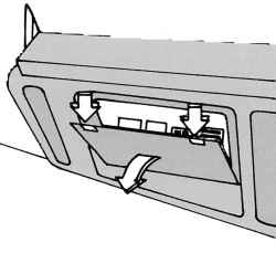
Box at the left pillar
It is located on the left in the footwell under the dashboard and consists of 2 blocks: Fuse box B and Fuse and relay box C.

Photo for example

Fuse box B

Diagram

Designation
| 1 | 25A driver’s door control unit |
| 2 | 10A Diagnostic connector (T16 / 16) |
| 3 | 25A ABS control unit |
| 4 | 40A ABS control unit |
| 5 | Reserve |
| 6 | Reserve |
| 7 | 30A headlight washer pump |
| 8 | 15A anti-theft alarm relay 1 |
| 9 | Reserve |
| 10 | 15A control unit with display for radio and navigation system |
| 11 | 7.5A control unit for mobile phone control electronics, tachograph control unit |
| 12 | 30A heating switch and heating power change, supply air fan relay |
| 13 | 7.5A auxiliary heater timer |
| 14 | 30A driver’s seat heating regulator, front passenger seat heating regulator |
| 15 | 10A load platform lighting switch |
| 16 | 10A heating switch and heating power change, air conditioning control unit, CD changer |
| 17 | 10A indoor light switch |
| 18 | Reserve |
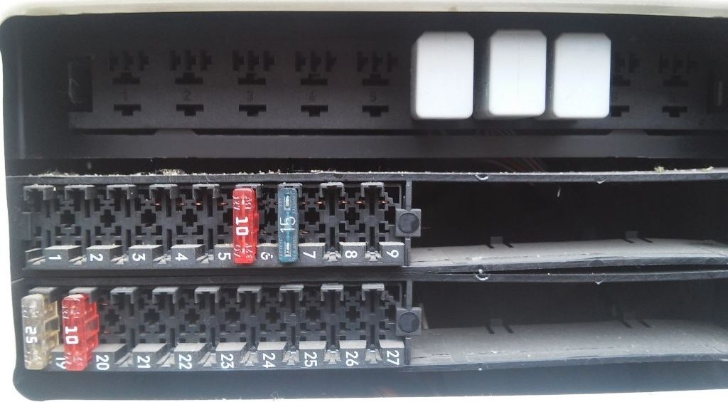
Fuse and relay box C
Photo for example
Diagram

Appointment
Relay
- Horn relay
- Wiper motor changeover relay 2
- Fuel pump relay
- Wiper motor changeover relay 1
- Power supply relay, cl. fifty
- Power supply relay terminal 15
- Relay for power supply of electronic components of the engine
- Power supply relay 2, cl. fifteen
Protected components
| 1 | 15A High tone signal |
| 2 | 25A Electronic ignition lock Control unit el. steering column lock |
| 3 | 10A Electronic ignition lock Control unit in dash panel insert Engine control unit (from May 2012,) |
| 4 | 5A Light switch Central control panel of the front panel |
| 5 | 30A Wiper motor |
| 6 | 15A Booster fuel pump |
| 7 | 5A Steering column control unit |
| 8 | 20A Engine control unit |
| 9 | 20 / 25A Fuse 6 on fuse box B (from November 2008 to May 2009) Fuse box D (from May 2009 to November 2013) |
| 10 | 10A Air mass meter (from May 2012) Reducing agent level estimation module (from May 2012) Heating resistor for crankcase ventilation (from May 2012) Fuel pressure regulator Exhaust gas recirculation cooler changeover valve (from May 2012) Check valve for reducing agent supply (from May 2012) ) Pump for exhaust gas recirculation cooler (from May 2012) Pump for reducing agent (from May 2012) |
| 11 | 15A Unloading relay 2, terminals 15 (only for vehicles of the weight class 3.8 t) Fuse 1 in fuse holder D Fuse 2 in fuse holder D |
| 12 | 10A Airbag control unit |
| 13 | 15A Stowage compartment lighting switch Cigarette lighter |
| 14 | 5A Light switch Control unit in instrument cluster Diagnostic connector |
| 15 | 5A Heater switch and operating mode selection Headlamp range adjuster Actuator motor for headlight range control for left and right |
| 16 | 10A Main switch for stop-start system Switch for gearbox neutral position Sensor for oil level and temperature Fuel pump relay Relay for pumping coolant after off Engine control unit Glow plug control unit Power supply relay, cl. 50 Starter relay 1 (from November 2013) Starter relay 2 (from November 2013) Solenoid valve for boost pressure control Coolant circuit valve Exhaust gas flap valve (from November 2013) Fuel metering valve Exhaust gas recirculation cooler changeover valve Lambda probe heater |
| 17 | 10A Airbag control unit |
| 18 | 7.5A Brake light switch (from July 2006 to November 2011) Brake pedal limit switch -F63- (from July 2006 to November 2011) Relay for unloading cl. 15 Voltage stabilizer (from November 2011) Relay for special superstructures, cl. 15 (from November 2011) Relay, unloading 3 for cl. 15 (from November 2011) |
| 19 | 7.5A Onboard supply control unit (interior lighting) |
| 20 | 25A Onboard supply control unit |
| 21 | 5A Air Mass Sensor Engine Control Unit |
| 22 | 5A Brake light switch (up to June 2006) Brake pedal switch (up to June 2006) Lateral acceleration sensor (from July 2006) Longitudinal acceleration sensor (from July 2006) ABS control unit (from July 2006) |
| 23 | 25A Starter Onboard supply control unit |
| 24 | 10A Reserve, terminal -15- Battery regulation system control unit (from May 2013,) |
| 25 | 30A 12V socket |
The fuse number 13, 15A, is responsible for the cigarette lighter.
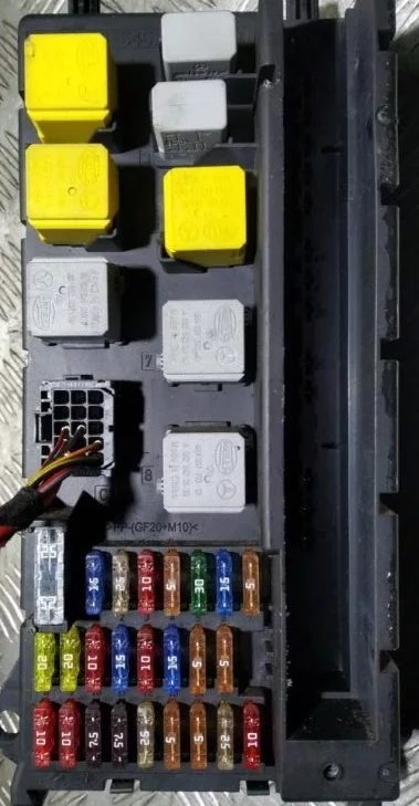
Fuse and relay box D
Under the driver’s seat
Type 1
Models released before 05.2011
The photo
Diagram

Designation
Relay
- Relay for special superstructures, cl. fifteen
- Relay for special superstructures, cl. 61
- Interior lighting relay, Tipping device relay (up to October 2007), Tailgate relay
- Headlight cleaning relay
- Rotating beacon relay
- Anti-theft alarm relay 1
- Coolant pump relay
- Coolant circulation relay after off engine
- Siren relay
- Not used
Circuit breakers
| 1 | 5A Power window control panel in driver’s door Heated rear window relay (up to June 2006) Heated rear window relay 2 (from July 2006) |
| 2 | 30A Swing door rear window wiper motor |
| 3 | 5A Timer Gearbox neutral switch Display control unit Control unit for mobile phone control electronics (up to May 2011) Rear view camera |
| 4 | 7.5A Switch for adjusting the operating speed (from July 2006) Control sensor for power take-off (from July 2006) Heated rear window relay (until June 2006) Trailer recognition control unit Tachograph control unit (from July 2006) |
| 5 | 5 / 10A Selector Control unit mech. Electronically controlled gearbox |
| 6 | 5A Battery regulation control unit (up to May 2013) Crankcase ventilation heating resistor |
| 7 | 10A Fuel filter heating element |
| 8 | 5 / 10A Button for tipping device Relay for special superstructures, cl. 15 Plug, 6-pin (from May 2007) Plug, 7-pin (tail lift connector) |
| 9 | 15A Roof fan switch for supply ventilation of the cargo compartment, Siren relay |
| 10 | 25A For the manufacturer of superstructures and special equipment |
| 11 | 15A Relay for special superstructures, cl. fifteen |
| 12 | 10A Relay for special superstructures, cl. 61 |
| 13 | 10 / 30A Evaporator fan control unit (from May 2007 to May 2011) Relay for repeaters, direction indicators on the roof (until May 2007) |
| 14 | 20A Trailer recognition control unit (up to August 2006) Connector, 9-pin (preparation for post-factory installation of trailer hitch from September 2006) Hitch socket (from September 2006) |
| 15 | 25A Trailer recognition control unit |
| 16 | 7.5A Parking aid control unit Tire pressure monitor control unit |
| 17 | 25A Control unit for programmable special functions |
| 18 | 25A Control unit for programmable special functions |
| 19 | 5 / 25A Roof electrical control unit |
| 20 | 7.5 / 10A Relay for pumping coolant after off. Engine Entrance and Legroom Light Relay (from May 2009,) |
| 21 | 15 / 30A Rear window defogger relay |
| 22 | 15A Rear window heating relay (up to June 2006) Rear window heating relay 2 |
| 23 | 10 / 15A Load box lighting switch (from November 2008) 12V socket 2 |
| 24 | 15A Socket 12V 4 |
| 25 | 15A Socket 12V 3 |
| 26 | 25A Additional heater control unit |
| 27 | 20 / 25A Additional heater control unit |
| 28 | 30 / 40A Evaporator fan control unit (up to April 2007) Gearbox hydraulic pump relay (from May 2007) |
| 29 | 15A Control unit mech. Electronically controlled gearbox |
| 30 | 40A Gearbox hydraulic pump relay (up to April 2007) Battery regulation control unit |
| 31 | 15 / 30A Control unit for rear intake fan Control unit for left sliding door Rear intake fan |
| 32 | 5A Control unit for battery control |
| 33 | 15A Right sliding door control unit |
| 34 | 15A Reductant heating system control unit (from April 2009) |
| 35 | 3 / 15А Reductant heating system control unit (from April 2009) |
| 36 | Not used |
Type 2

Diagram

Assignment
| 1 | 5A Window regulator control panel in the driver’s door Relay 2 for heated rear window |
| 2 | 30A Rear window wiper motor in swing door |
| 3 | 5A Timer Gearbox neutral position switch Display panel Rear view camera |
| 4 | 7.5A Switch for adjusting the operating speed PTO monitor sensor Trailer detection control unit Tachograph control unit |
| 5 | 5 / 10A Selector Control unit mech. Electronically controlled gearbox Bonnet limit switch (from November 2011) |
| 6 | 5 / 10A Heating resistor for crankcase ventilation system Control unit for battery regulation (from May 2011 to May 2013) |
| 7 | 10A Fuel filter heating element |
| 8 | 5 / 10A Tipping device button Parking aid control unit (from May 2013) Special superstructure relay, cl. 15 (up to November 2011) 6-pin connector -T6ah- 7-pin connector -T7f- (tail lift connector) |
| 9 | 15A Roof fan switch for supply ventilation of the cargo compartment (until November 2011) Siren relay (until November 2011) Not used (from November 2011) |
| 10 | 25A For the manufacturer of superstructures and special equipment |
| 11 | 15A Relay for special superstructures, cl. fifteen |
| 12 | 10A Relay for special superstructures, cl. 61 |
| 13 | Reserve |
| 14 | 20A Connector, 9-pin -T9b- (preparation for post-factory installation of trailer hitch) Hitch socket |
| 15 | 25A Trailer recognition control unit |
| 16 | 7.5A Parking aid control unit Tire pressure monitor control unit |
| 17 | 25A Control unit for programmable special functions |
| 18 | 25A Control unit for programmable special functions |
| 19 | 5 / 25A Roof electrical control unit |
| 20 | 7.5 / 10A Relay for pumping coolant after off. motor relay input illumination and footwell |
| 21 | 30A Rear window defogger relay |
| 22 | 15A Rear window heating relay 2 |
| 23 | 10 / 15A Load box lighting switch 12 V socket 2 -U18- |
| 24 | 15A Socket 12V 4 |
| 25 | 15A Socket 12V 3 |
| 26 | 25A Additional heater control unit |
| 27 | 20 / 25A Additional heater control unit |
| 28 | 30 / 40A Gearbox hydraulic pump relay, Starter relay 1 |
| 29 | 15A Control unit mech. Electronically controlled gearbox |
| 30 | 5A Battery regulation system control unit |
| 31 | 15 / 30A Control unit for left sliding door (from May 2012) Control unit for rear supply fan Rear supply fan |
| 32 | 5A Control unit for battery control |
| 33 | 7.5 / 15 / 30A Not used Right sliding door control unit (from May 2012) Transfer case interlock relay (from January 2012) Air compressor (from January 2012) |
| 34 | 7.5 / 15A Control unit for reducing agent heating system Gearbox sensor for differential lock |
| 35 | 3 / 15A Control unit for reducing agent heating system Compressor protection control unit (from January 2012) |
| 36 | 5A Not used (until January 2012) Compressor switch (from January 2012) |
| 37 | Reserve |
| 38 | Reserve |
| 39 | 7.5 / 15A Roof fan switch for supply ventilation of the cargo compartment (from November 2011) Siren relay (from November 2011) |
| 40 | Reserve |
| 41 | Reserve |
| 42 | 30A Evaporator fan control unit -J349- |
| 43 | Reserve |
| 44 | Reserve |
| 45 | Reserve |
| 46 | Reserve |
| 47 | Reserve |
| 48 | Reserve |
| 49 | Reserve |
| 50 | Reserve |
| 51 | Reserve |
| 52 | Reserve |
| 53 | Reserve |
| 54 | Reserve |
| 55 | Reserve |
| 56 | Reserve |
Relay under the seat
Additional relays can be installed under the seat itself.

Diagram

Appointment
| A | Battery isolation relay |
| B | Starter relay 1 |
| C | Starter relay 2 |
| 1 | Not used |
| 2 | Relay for unloading cl. fifteen |
| 3 | Relay for unloading 3 terminals 15 Relay for pneumatic compressor |
| 4 | Gearbox hydraulic pump relay Switching relay for daytime running light |
| 5 | Heated rear window relay |
| 6 | Heated rear window relay 2 |
| 7 | Unloading relay 2 terminals 15 |
| 8 | Not used |
| 9 | Heated windshield relay |
| 10 | Supply fan relay |
| 11 | Not used |
| 12 | Not used |
| 13 | Not used |
| 14 | Not used |
| 15 | Relay for special superstructures, cl. fifteen |
| 16 | Relay for special superstructures, cl. 61 |
| 17 | Tailgate relay Interior lighting relay |
| 18 | Relay for headlight cleaning system Relay for unlocking pneumatic compressor |
| 19 | Siren relay 2 Entrance and footwell light relay Air compressor relay – regeneration |
| 20 | Anti-theft alarm relay 1 |
| 21 | Coolant pump relay |
| 22 | Coolant circulation relay after off engine |
| 23 | Siren relay ABS cut-off relay |
| 24 | Relay blocking 1 transfer case |
| 25 | Locking relay 2 transfer case |
| 26 | Relay for reversing warning device shutdown Relay for blocking 3 transfer case |
We have posted a video on our YouTube channel. Watch and subscribe.
If you have something to add – write in the comments.
Which is the fuse for the headlights ?? (2014 crafter)
lights are all done by the body control module and when they start messing around good luck in finding the fault in the wiring if there is one and not the bcu playing up
Where is the fuse for the radio on a 15 plate crafter ?
Back of radio
Hi can please tell me the location of the front temperature sensor on a 2020 model VW Crafter Right hand drive
Thank you
Hi, can any please tell me where the fuse boxes are located for the cigarette lighter and central locking
hey which fuse is for the speed limiter the bus now goes up to 120 and in germany this is really too slow
I need an advice please, crafter 2016 tail light on right is flashing ( 30 sec on 5 of ) and no fog light on right side and left. Thanks.
Reverseing lights fuse .
Can anybody tell me we’re the fuse is for the washers on an 61 plate crafter please. Thanks