Toyota RAV4 3 generations was produced in 2006, 2007, 2008, 2009, 2010, 2011, 2012 and was designated as CA30W / XA30W. During this time, the model has been restyled. In this article you will find information with the location of electronic control units, designation of fuses and relays Toyota Rav 4 with box diagrams and photo examples of execution. Note the cigarette lighter fuse.

The location of the electronic controls and the purpose of the fuses and relays may differ from that shown, depending on the year of manufacture, equipment level and the region in which your vehicle was supplied.
Contents
Passenger compartment
Location
LDH

RHD

Assignment
- LHD: Relay box # 2
- Relay box No. 1
- Fuse Box / Body ECM
- Key transponder amplifier
- Steering lock control unit
- Power steering control unit
- Distribution block
- Distribution block
- Tire pressure monitoring system control unit
- Brake light relay
- All-wheel drive control unit
- Auto wiper relay
- Selector lever lock control unit
- Central airbag control unit
- Air conditioner amplifier
- RHD: Starter Relay (ST) (Petrol, Before Dec 2008: Diesel with keyless entry and start system)
Jumper (Before Dec 2008: Diesel Engines without Keyless Entry and Start System) - RHD: Turn signal relay (hazard warning lights)
- RHD: Anti-theft control unit
- RHD: Double interlock control unit
Fuse box
In the diagram it is designated under number 3. It is located under the dashboard.

Top of the box
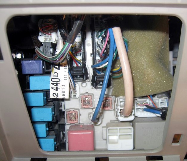
Photo example
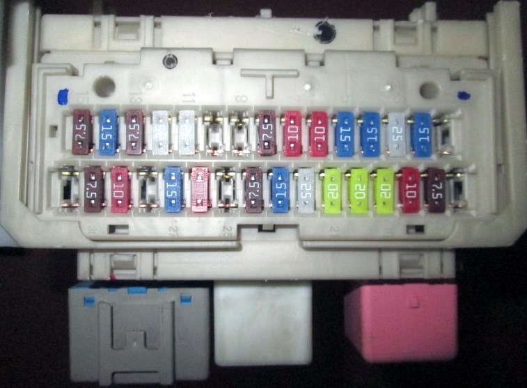
Diagram

Designation
| 1 | Not used |
| 2 | 15A S − HTR – Heated seats |
| 3 | 25A WIP – Screen wiper |
| 4 | 15A RR WIP – Rear wiper |
| 5 | 15A WSH – Windshield Washer, Rear Window Washer |
| 6 | 10A ECU-IG1 – Cooling fan, ABS, anti-slip system, stability control system, hill traction assist system, hill trail assist system, AWD system with electronic torque distribution, air conditioning system, body electronics , sunroof, auto-dimming interior mirror, brake / side lights, heated windscreen wiper blades, power steering, clutch release system, headlight cleaner, heater, clock |
| 7 | 10A ECU-IG2 – Air conditioning, heated rear window |
| 8 | 7,5A OBD – Diagnostic connector |
| 9 | 10A STOP – Stop lamps, auxiliary brake light, gear selector lock, multiport fuel injection system / sequential multiport fuel injection system, ABS, anti-slip system, stability control system, hill traction assist system, traction assist control system on the slope |
| 10 | Not used |
| 11 | 25A DOOR – Body electronics unit, central locking |
| 12 | 25A ACC-B – Fuses: “ACC”, “CIG” |
| 13 | 7,5A 4WD – All-wheel drive system with electronic torque distribution |
| 14 | 15A FR FOG – Front fog light |
| 15 | 7,5A AM1 – Starting system |
| 16 | 10A TAIL – Side light, license plate light, front fog light, rear fog light |
| 17 | 7,5A PANEL – Audio system, instrument panel illumination, clock |
| 18 | 10A GAUGE1 – Reversing lamps, charging system |
| 19 | 20A D FR DOOR – Windows (front doors) |
| 20 | 20A RL DOOR – Window regulator (rear left door) |
| 21 | 20A RR DOOR – Window Regulator (Rear Right Door) |
| 22 | 25A S / ROOF – Hatch |
| 23 | 15A CIG – Cigarette lighter |
| 24 | 7.5A ACC – Audio system, power outlets, power mirrors, gear selector lock, body electronics, clock |
| 25 | Not used |
| 26 | 10A MIR HTR – Heated mirrors |
| 27 | 15A PWR OUTLET – Socket |
| 28 | Not used |
| 29 | 10A RR FOG – Rear fog light |
| 30 | 7,5A IGN – Airbags, multiport fuel injection system / sequential multiport fuel injection system, brake lights / side lights, starting system |
| 31 | 7,5A GAUGE2 – Instrument Cluster |
The fuse number 23, 15A, is responsible for the operation of the cigarette lighter.
On the other side of the box, individual elements can be attached.
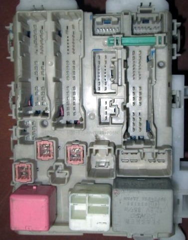
Diagram

Circuit breakers
- 30A POWER – Power windows
- 30A DEF – Heated rear window, fuse: “MIR HTR”
- 30A P / SEAT – Power Seat
Relay
- R1 – Ignition (IG1)
- R2 – Heater (mechanical air conditioner) / Jumper (automatic air conditioner)
- R3 – LHD: Direction indicators (hazard warning lights)
Relay box
Located next to the fuse box.
Diagram

Functions
| R1 | Starter (ST CUT) |
| R2 | LHD: Starter Motor (ST) (Petrol, Before Dec 2008: Diesel with keyless entry and start system) |
| LHD: Jumper (Before Dec 2008: Diesel Engines without Keyless Entry and Start System) | |
| R3 | Front fog light (FR FOG) |
| R4 | Rear fog light (RR FOG) |
| Socket (115V) | |
| R5 | Auxiliary relay (ACC) |
| R6 | Socket (PWR OUTLET) |
Additional elements

Components
- Distribution block
- Sunroof control unit
- Antenna and receiver for tire pressure monitoring system
- Central locking receiver
- Audio amplifier
Engine compartment
Location

Assignment
- Fuse and relay box No. 1
- 2AD-FHV, 2AD-FTV: Injector control unit (EDU) (from December 2008)
- 2AD-FHV: Injector Control Unit (EDU) (up to Dec 2008)
- 2AD-FTV: Injector Control Unit (EDU) (up to Dec 2008)
- Valvematic
- ABS control unit
- Fuse and relay box No. 2
- The engine control unit
- Transmission control unit
- Cooling fan control unit or left cooling fan control unit
- Glow plug relay
- Cooling fan right control unit
- Headlight wiper relay
Fuse and relay box 1

Mounts on the right side under the hood.

Diagram

Circuits protected
| 1 | Not used |
| 2 | Not used |
| 3 | Not used |
| 4 | 7,5A ECU-B2 – Air conditioning, power windows |
| 5 | 7,5A ALT − S – Charging system |
| 7,5A RSE – Audio system (JBL) | |
| 6 | 20A STR LOCK – Steering lock system (with keyless entry and start system) |
| 7 | Not used |
| 8 | DCC |
| 9 | 20A RAD NO.1 – Audio system |
| 10 | 10A ECU-B – Wireless remote control system, power steering, body electronics, clock, instrument cluster, keyless entry and start system, central locking, clock, audio system, navigation system, instrumentation |
| 11 | 10A DOME – Ignition switch illumination, engine start button illumination (with keyless entry and start system), “ENGINE START STOP” switch illumination (with keyless entry and start system), interior lighting, vanity mirror illumination, luggage compartment illumination, personal lighting, illumination of the lower part of the cabin |
| 12 | – |
| 13 | 10A HEAD LH – High beam left |
| 14 | 10A HEAD RH – High beam right |
| 15 | 10A HEAD LL – Low beam left |
| 16 | 10A HEAD RL – Low beam right |
| 17 | – |
| 18 | 15A AC INV – Socket (115V) |
| 19 | 30A TOWING – Trailer connector |
| 20 | 25A STV HTR – Autonomous heater for passenger compartment |
| 21 | Not used |
| 22 | 20A DEICER – Heated zone of rest of windshield wiper blades |
| 23 | 50A HTR – Air conditioning system |
| 24 | 50A PTC3 – Auxiliary heater |
| 25 | 50A PTC2 840W: Auxiliary heater |
| 30A PTC2 300W: Auxiliary heater | |
| 26 | PTC1 50A 840W: Auxiliary heater |
| PTC1 30A 300W: Auxiliary heater | |
| 27 | 50A HEAD MAIN – Fuses: “HEAD LL”, “HEAD RL”, “HEAD LH”, “HEAD RH” |
| 28 | Not used |
| 29 | 30A RDI – Cooling fan |
| 50A FAN2 – 2GR-FE with hitch option: Cooling fan | |
| 30 | 30A CDS – Cooling fan |
| 50A FAN1 – 2GR-FE with hitch option: Cooling fan | |
| 31 | 30A H − LP CLN – Headlight cleaners |
| R1 | Light switch / high beam |
| R2 | Headlights / low beam |
| R3 | Daytime running lights (No. 4) |
| R4 | Daytime running lights (No. 3) |
| R5 | Except 2GR-FE: Cooling fan (no. 3) |
| R6 | Except 2GR-FE: Cooling fan (no. 2) |
| R7 | Except 2GR-FE: Cooling fan (no. 1) |
| R8 | Not used |
| R9 | Heated zone of rest of the windshield wiper blades |
| R10 | Daytime running lights (No. 2) |
| R11 | Except 2GR-FE: Auxiliary heater (PTC NO.3) |
| R12 | Except 2GR-FE: Auxiliary heater (PTC NO.2) |
| 2GR-FE: Cooling fan (no. 2) | |
| R13 | 2GR-FE: Cooling fan (no. 1) |
| Except 2GR-FE: Auxiliary heater (PTC NO.1) |
Fuse and relay box 2

Installed on the left side of the engine compartment.

Diagram

Designation
| 1 | 30A P-SYSTEM – 3ZR-FAE: Valvematic |
| 2 | 30A AMP – Audio System (JBL) |
| 3 | 30A AM2 – Starting system |
| 4 | 15A IG2 – Engine starting system, multiport fuel injection system / sequential multiport fuel injection system |
| 5 | 10A HAZ – Alarm |
| 6 | 10A ETCS – Multiport fuel injection system / sequential multiport fuel injection system |
| 7 | 7,5A AM2-2 – Starting system |
| 8 | – |
| 9 | 10A Multiport fuel injection system / sequential multiport fuel injection system |
| 10 | 10A EFI NO.2 – Multiport fuel injection system / sequential multiport fuel injection system |
| 11 | 7.5A EFI NO.3 – A / T; from Dec 2008: Multiport fuel injection system / sequential multiport fuel injection system |
| 7,5A STA – Starting system, multiport fuel injection system / sequential multiport fuel injection system | |
| 12 | 80A GLOW – Preheating system |
| 13 | 60A EMPS – Power steering |
| 14 | 80A MAIN – Fuses: “HEAD MAIN”, “ECU-B2”, “DOME”, “ECU-B”, “RAD NO.1” |
| 15 | 120A ALT – Gasoline engines, vehicles without coupling option: Fuses: “ABS 1”, “ABS 2”, “RDI”, “CDS”, “HTR”, “TOWING” |
| 140A ALT – Diesel engines, vehicles with hitch option: Fuses: “ABS 1”, “ABS 2”, “RDI”, “CDS”, “HTR”, “TOWING” | |
| 16 | 50A P / I – Fuses: “EFl MAIN”, “HORN”, “A / F”, “EDU” |
| 17 | Not used |
| 18 | 30A ABS 2 – Antilock Braking System, Traction Control, Vehicle Stability Assist, Hill Descent Assist, Hill Descent Assist |
| 19 | 50A ABS 1 – Antilock Braking System, Traction Control System, Vehicle Stability Assist, Hill Descent Assist, Hill Descent Assist |
| 20 | 20A EFl MAIN – Multiport fuel injection system / sequential multiport fuel injection system, fuses: “EFI NO.1”, “EFI NO.2”, “EFI NO.3” |
| 21 | 10A HORN – Signal |
| 22 | 25A EDU – Multiport fuel injection system / sequential multiport fuel injection system |
| 23 | 20A A / F – Gasoline: Multiport fuel injection system / sequential multiport fuel injection system |
| 20A A / F – Diesel: Multiport fuel injection system / sequential multiport fuel injection system | |
| 15A IGT / INJ – 3ZR-FAE: Multiport fuel injection system / sequential multiport fuel injection system | |
| R1 | Vehicle Stability System (VSC MTR) |
| R2 | Not used |
| R3 | Vehicle Stability System (VSC FAIL) |
| R4 | Ignition (IG2) |
| R5 | Anti-lock braking system (BRK) |
| R6 | A / C Compressor Clutch (MG CLT) |
| R7 | Fuel pump |
That’s all. And if you know how to make the material better, write in the comments.
Great description of the fuses & relays and their locations. Very useful & appreciated.
Would you know how to or where I can get some information on how to have the fog lights on at all times (with the fog light switch, when ignition is on) without having them turn off when high beams are turned on or when the lights aren’t on?
bonjour la famille,pour mon cas je cherche fuse box pour toyota harrier 240g,pouvez vous me donner ?
Bonjour la famille pour mon cas je cherche le fusible des injecteurs pour vanguard