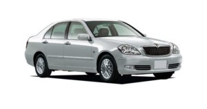
Toyota Progress was produced in 1998, 1999, 2000, 2001, 2002, 2003, 2004, 2005, 2006, and 2007. It shared a platform with the Toyota Brevis. This article describes the fuses and relays in the Toyota Progress Brevis, including fuse box diagrams, their locations, and photo examples. We’ll highlight the fuse for the cigarette lighter.
The purpose of some elements in the diagrams may differ from the one presented and depends on the year of manufacture, configuration and country of delivery. In case of difficulty, contact your nearest dealer.
Contents
Passenger compartment
Location
Layout
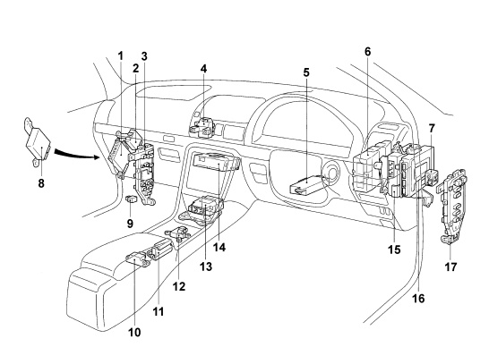
Assignment
- Audio amplifier (Super Live Sound)
- Headlight range control relay (models from 04/2001)
- Passenger side fuse box
- Central fuse box
- Steering column adjustment control unit
- 4WD system control unit (models before 04/2001)
- VSC system buzzer
- 4WD system control unit (models from 04/2001)
- Power circuit relay (models from 04/1999)
- Side movement sensor
- Selection lock control unit
- Deceleration sensor
- SRS control unit
- Integrated control unit
- Adaptive cruise control unit
- ABS control unit
- Driver side fuse box
Driver side fuse box
This fuse box is located under the instrument panel, on the pillar and covered with a protective cover.
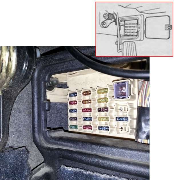
Check the purpose of the elements with your diagrams on the back of the block covers.
Diagram
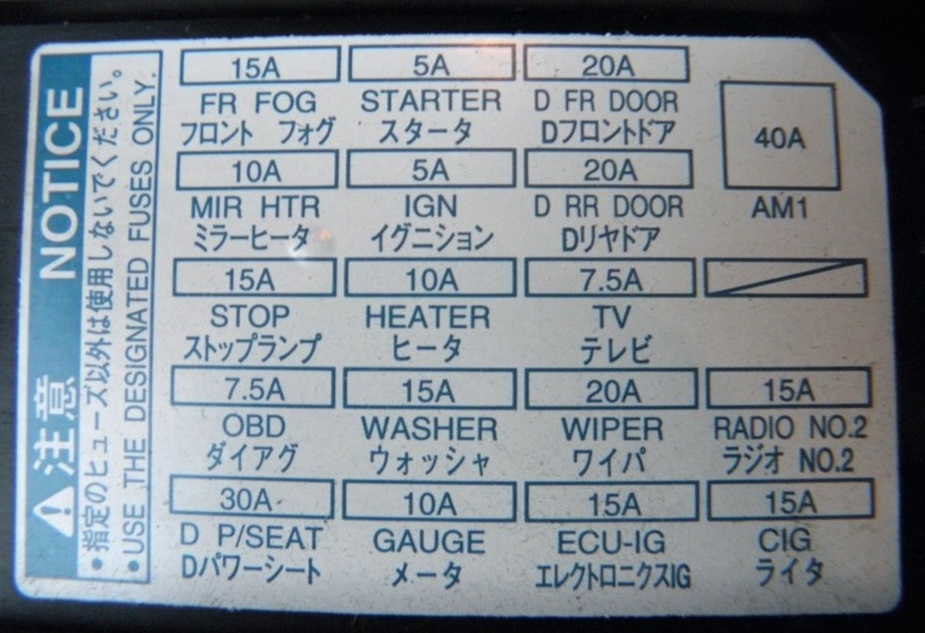
Designation
| FR FOG | 15A — Fog lights |
| STARTER | 5A — Starter |
| D FR P/W | 20A — Driver’s power window |
| TRK OPN | 20A — Trunk release (lid) |
| MIR HTR | 10A — Heated rearview mirrors |
| IGN | 5A — Engine management system |
| D RR P/W | 20A — Rear right power window |
| D RR DOOR | 20A — Rear lid control module |
| STOP | 15A — Brake lights |
| HEATER | 10A — Heating and air conditioning system |
| DOME | 7.5A — Interior lighting |
| OBD | 7.5A — Diagnostic connector |
| WASHER | 15A — Windshield washer |
| WIPER | 20A — Windshield wiper |
| RADIO No.2 | 15A — Radio |
| P/SEAT | 30A — Driver’s power seat |
| D-IG | 10A — Charging system/rear window shade |
| GAUGE | 10A — Instrument cluster |
| ECU-IG | 15A — ABS, TRC, VSC, cruise control |
| CIG | 15A — Cigarette lighter |
The cigarette lighter is controlled by a 15A fuse labeled CIG.
Passenger Side Fuse Box
Another fuse box is located under the instrument panel, on the left pillar.
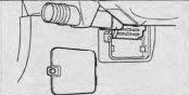
Photo for example
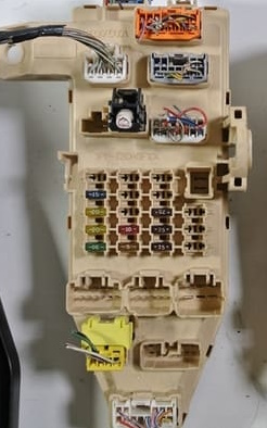
Allocation
| SEAT HTR | 15A — Heated Seats |
| P FR P/W | 20A — Front Right Power Window |
| P RR DOOR | 20A — Rear Right Power Door Control Module |
| DOME | 10A — Interior Lighting, Clock |
| P FR P/W | 20A — Front Left Power Window |
| P FR DOOR | 20A — Front Door Control Module |
| TAIL | 15A — Front and Rear Parking Lights, License Plate Light |
| FUEL OPN | 7.5A — Power Fuel Filler Door |
| P/SEAT | 30A — Front Passenger Power Seat |
| PANEL | 7.5A — Instrument Panel and Climate Control Lighting |
| RR FOG | 7.5A — Rear Fog Light |
Engine compartment
There may be 2 fuse and relay boxes installed in the engine compartment.
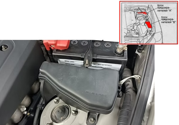
Photo
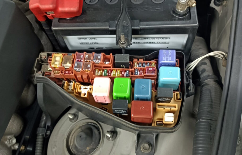
Fuse box A
Progres
Diagram
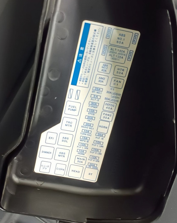
Appointment
| ABS NO.1 | Relay — ABS System (Control) |
| ABS NO.2 | 40A — ABS System (Pump/Module) |
| ABS SOL | Relay — ABS Solenoid Control |
| ABS MTR | Relay — ABS Pump Motor |
| ALT | 140A — Generator (Main Charging Circuit) |
| ALT-S | Relay — Generator Control |
| AM2 | 30A — Ignition Circuit |
| HTR | 50A — Heater (Stove) |
| FAN1 | Relay — Cooling Fan #1 |
| FAN2 | 30A — Cooling Fan #2 |
| DEFog | 40A — Rear Window Defogger |
| FUEL PUMP | Relay — Fuel Pump |
| EFI | Relay — Injection System |
| ETCS | 10A — Electronic Throttle |
| INJ | 20A — Injectors |
| RADIO No.1 | 20A — Audio System |
| TURN-HAZ | 10A — Turn Signals and Hazard Lights |
| HORN | 10A — Horn |
| ECU-B | 10A — ECU Power (Constant) |
| MAIN | 50A — Main Power Circuit |
| HEAD | Relay — Headlights |
| ST | Relay — Starter |
| DIMMER | Relay — Low/High Beam Switch |
| TRC MTR | Relay — Traction Control Motor |
| MPX-B | 15A — Multiplex System (Body Electronics) |
| H-LP LH | 15A — Left Headlight |
| H-LP RH | 15A — Right Headlight |
| H-LP LO LH | 15A — Left Low Beam |
| H-LP LO RH | 15A — Right Low Beam |
| H-LP HI LH | 15A — Left High Beam |
| H-LP HI RH | 15A — Right High Beam |
| FR FOG | Relay — Front Fog Lights |
| H-LP CLN | 20A — Headlight Washer |
| ST1 | 30A — Starter Circuit |
| ST2 | 30A — Starter Circuit |
| IG | Relay — Ignition |
Brevis
Diagram
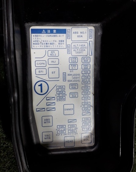
Decoding
| ABS NO.1 | 60A — ABS main circuit |
| ALT | 120–140A — Generator (battery charging) |
| HTR | 50A — Heating system (heater fan) |
| FAN1 | 40A — Engine cooling fan #1 |
| AM2 | 30A — Ignition circuit |
| MPX-B | 15A — Body electronics module (multiplex) |
| ECU-B | 15A — ECU power supply (constant) |
| HORN | 10A — Horn |
| ETCS | 10A — Electronic throttle |
| EFI | 20A — Fuel injection system |
| F/PMP | 25A — Fuel pump |
| TURN-HAZ | 10A — Turn signals and hazard warning lights |
| DOME | 7.5A — Interior lighting |
| ABS SOL | 7.5A — ABS valve control |
| H-LP LH | 15A — Left headlight |
| H-LP RH | 15A — Right headlight |
| H-LP LO LH | 15A — Left low beam |
| H-LP LO RH | 15A — Right low beam |
| FR DEF | 25A — Heated windshield |
| RR DEF | 25A — Heated rear window |
| DR DOOR | 25A — Driver’s door power package |
| S/ROOF | 25A — Sunroof |
| FAN2 | 30A — Cooling Fan #2 |
| EFI NO.2 | Relay — Injection System |
| C/OPN | Relay — Fuel Pump |
| EFI | Relay — Injection System Power |
| ST | Relay — Starter |
| DIMMER | Relay — Low/High Beam Switch |
| HEAD | Relay — Headlights |
| ABS MTR | Relay — ABS Pump Motor |
| TRC MTR | Relay — Traction Control |
Fuse box B
Photo – diagram
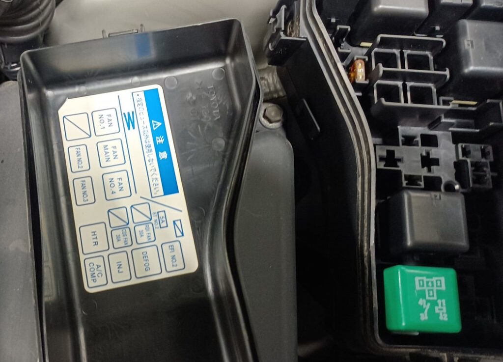
Description
| FAN NO.1 | Relay — Cooling Fan #1 |
| FAN NO.2 | Relay — Cooling Fan #2 |
| FAN NO.3 | Relay — Cooling Fan #3 |
| FAN NO.4 | Relay — Cooling Fan #4 |
| FAN MAIN | Relay — Main Fan System Relay |
| HTR | Relay — Heater (Blower Fan) |
| DEFog | Relay — Windshield Defogger |
| EFI NO.2 | Relay — Fuel Injection System |
| A/C COMP | Relay — Air Conditioning Compressor |
| INJ | Relay — Injectors |
| ST N1 | 5A Starting System Fuse |
If you know how to make the post better, write in the comments.