Toyota Hilux Surf 3 generations were produced in 1995, 1996, 1997, 1998, 1999, 2000, 2001, 2002 with the body designation 180/185. During this time, the model was updated 2 times. Also known as Toyota 4Runner. In this publication, we will show the location of the electronic control units, a description of the fuses and relays of the Toyota Surf with box diagrams and photo examples of their execution. Highlight the cigarette lighter fuse.

The arrangement of the boxes and the purpose of the elements in them may differ from that shown and depend on the year of manufacture and the level of equipment.
Contents
Passenger compartment
Location
General layout of boxes in the cabin
Left hand drive

Right hand drive

Assignment
- Airbag control unit
- All Wheel Drive Relay (ADD)
- LHD: Fuel pump relay
- Integrated relay
- Fuse box
- LHD: Relay for daytime running lights
- Emission control unit (3RZ-F, 1RZ)
Pre-heater timer (diesel)
LHD: Engine control unit (2RZ-FE)
RHD: Engine control unit (M / T) (3RZ-FE, 1RZ-E)
RHD: Engine and gearbox control unit (A / T) (3RZ-FE, 1RZ-E) - Air conditioner amplifier
- LHD: Differential lock control unit
- ABS control unit
- Deceleration sensor
- RHD: Four-wheel drive control unit
- RHD: Relay Box (Fuel Pump Relay (Circuit Opening))
- RHD: Antenna Relay
- RHD:
Australia: Distribution block
Except Australia: Distribution connector - RHD: Light Relay (Dim-Dip)
Fuse box
Located at the bottom of the panel behind a protective cover.
Photo example of execution

Diagram

Protected components
R1 – integrated relay
| 1 | 20A SEAT-HTR – Heated seats |
| 2 | 15A ACC – Cigarette Lighter, Clock, Power Mirrors, Reversing Lights, Gear Selector Lock |
| 3 | 7.5A ECU-B – Rear Fog Light, Airbag Indicator, Daytime Running Lights, Cruise Control, ABS |
| 4 | 20A 4WD – Front differential shut-off system, four-wheel drive, rear differential lock |
| 5 | 10A TURN – Direction indicators, hazard warning lights |
| 6 | 10A GAUGE – Instrument cluster, reversing lamps, cruise control, aerial, central locking, gearbox control unit, starting system, charging system, heater control unit |
| 7 | 15A ECU-IG – ABS, transmission selector lock |
| 8 | 20A WIPER – Wiper and washer |
| 9 | 10A IGN – Charge Indicator, Airbags, Multiport Fuel Injection System / Sequential Multiport Fuel Injection System |
| 10 | 30A POWER – Power windows, central locking |
The fuse number 2, 15A, is responsible for the cigarette lighter.
Some relays are attached to the back of the unit.

- R1 Horn
- R2 Direction indicators (hazard warning lights)
- R3 Power relay (power windows, central locking)
- R4 Heated rear window
Separately, in the relay box there is a fuel pump relay (petrol), an electromagnetic bypass valve (diesel) (until 08.1998) and a start-inhibit relay (until 08.1998)
Engine compartment
Location
Layout of boxs under the hood

Appointment
- Fuse and Relay Box (Petrol, LHD Diesel)
- Relay box No. 1 (LHD Diesel)
- Relay box No. 2
- Fuse and Relay Box (RHD Diesel)
- Relay box # 1 (RHD)
- Relay box # 3 (LHD)
- Headlight wiper relay (LHD)
- Relay box # 3 (RHD)
- Relay box No. 4 (Israel)
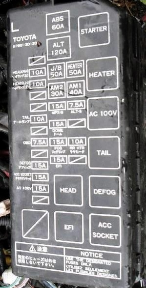
Fuse and relay box
Type 1
Photo example
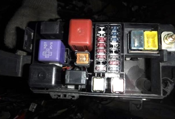
Covery

Diagram

Designation
| 1 | – |
| 2 | 15A DEFOG – Heated rear window |
| 3 | 10A STOP – Brake light |
| 4 | 7,5A ALT-S – Charging system |
| 5 | – |
| 6 | 7,5A OBD – Petrol: Diagnostic connector |
| 20A AM2 – Diesel: Multiport fuel injection system / sequential multiport fuel injection system | |
| 7 | 15A EFI – Multiport fuel injection system / sequential multiport fuel injection system |
| 8 | 15A HORN – Sound signal, alarm |
| 9 | 15A DOME – Audio system, antenna, interior lighting, clock, ignition switch lighting, personal lighting, door lighting |
| 20A AM2 – Multiport fuel injection system / sequential multiport fuel injection system | |
| 10 | 10A TAIL – Side light, license plate light, brake light, air conditioning, audio system, clock, cigarette lighter, instrument panel light |
| 11 | – |
| 12 | 10A A.C – Air conditioner |
| 13 | 7,5A STA – Multiport fuel injection system / sequential multiport fuel injection system, starting system, instrument cluster |
| 14 | 10A HEAD (RH) – Right headlight |
| 15 | 10A HEAD (LH) – Left headlight |
| 16 | 10A HEAD (LO RH) – Low beam right |
| 17 | 10A HEAD (LO LH) – Low beam left |
| 18 | 60A ABS – Petrol: ABS |
| 80A GLOW, ABS – Diesel: Preheater, ABS | |
| 19 | 80A ALT – 45A, 55A: Fuses: “ABS”, “AM1”, “STA”, “ECU-B”, “POWER”, “RADIO”, “ACC”, “GAUGE”, “TURN”, “ECUI G “,” WIPER “,” 4WD “,” HEATER “,” AC “,” TAIL “,” PANEL “,” STOP “,” ALT-S “ |
| 100A ALT – 70A: Fuses: “ABS”, “AM1”, “STA”, “ECU-B”, “POWER”, “RADIO”, “ACC”, “GAUGE”, “TURN”, “ECUI G”, “WIPER”, “4WD”, “HEATER”, “AC”, “TAIL”, “PANEL”, “STOP”, “ALT-S” | |
| 20 | 50A HEATER – Air conditioner |
| 21 | 40A AM1 – Ignition switch, starting system, headlamp cleaner relay, fuel heating, fuses: “ECU-B”, “GAUGE” “POWER” |
| 22 | 30A AM2 – Ignition lock |
| Relay | |
| R1 | Dimmer |
| R2 | Side light (TAIL) |
| R3 | Headlights (HEAD) |
| R4 | Heater |
| R5 | Starter |
| R6 | Engine control unit (EFI) |
Type 2
Photo

Covery
Diagram
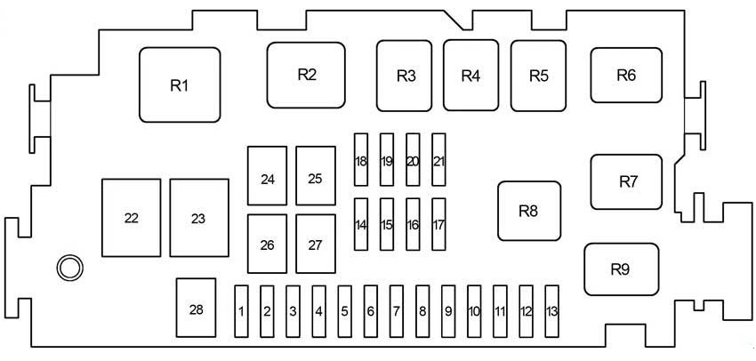
Decoding
| 1 | – |
| 2 | 10A HEAD (RH) – Right headlight |
| 3 | 10A HEAD (LH) – Left headlight |
| 4 | 10A HEAD (RL) – Low beam right |
| 5 | 10A HEAD (LL) – Low beam left |
| 6 | 10A TAIL – Side light, license plate light |
| 7 | 7,5A STA – Multiport fuel injection system / sequential multiport fuel injection system, starting system, instrument cluster |
| 8 | 10A A / C – Air Conditioning |
| 9 | Not used |
| 10 | Not used |
| 11 | Not used |
| 12 | Not used |
| 13 | Not used |
| 14 | 15A HORN – Sound signal |
| 15 | 15A DOME – Audio system, interior lighting, clock, personal lighting, door lighting, daytime running lights, instrument cluster |
| 16 | 7,5A OBD – Diagnostic connector |
| 17 | 15A EFI – 2RZ-FE, 3RZ-FE: Multiport fuel injection system / sequential multiport fuel injection system |
| 15A ECD – 1KZ-TE, 5L-E: Multiport fuel injection system / sequential multiport fuel injection system | |
| 20A AM2 – Diesel: Ignition switch, multiport fuel injection system / sequential multiport fuel injection system | |
| 18 | 7,5A ALT − S – Charging system |
| 19 | 15A DEFOG – Heated rear window |
| 20 | 10A STOP – Brake light |
| 21 | Not used |
| 22 | 60A ABS – Petrol: ABS |
| 80A GLOW, ABS – Diesel: Preheater, ABS | |
| 23 | 80A ALT – 45A, 55A: Fuses: “ABS”, “AM1”, “STA”, “ECU-B”, “POWER”, “RADIO”, “ACC”, “GAUGE”, “TURN”, “ECUI G “,” WIPER “,” 4WD “,” HEATER “,” AC “,” TAIL “,” PANEL “,” STOP “,” ALT-S “ |
| 100A ALT – 70A: Fuses: “ABS”, “AM1”, “STA”, “ECU-B”, “POWER”, “RADIO”, “ACC”, “GAUGE”, “TURN”, “ECUI G”, “WIPER”, “4WD”, “HEATER”, “AC”, “TAIL”, “PANEL”, “STOP”, “ALT-S” | |
| 24 | 50A HEATER – Heater, fuse: “A.C” |
| 25 | 40A AM1 – Starting system |
| 26 | 30A CDS FAN – Cooling fan |
| 27 | 30A AM2 – Ignition, Multiport fuel injection system / sequential multiport fuel injection system |
| 28 | – |
| Relay | |
| R1 | Gasoline: Starter |
| R2 | Heater |
| R3 | Cooling fan (CDS FAN) |
| R4 | Side light (TAIL) |
| R5 | – |
| R6 | – |
| R7 | Engine control unit (EFI) |
| Engine control unit (ECD) | |
| R8 | Headlights (HEAD) |
| R9 | Dimmer |
Relay box No. 1

- R1 – Starter (ST)
- R2 – Glow plugs (SUB GLW)
Relay box No. 2
- R1 – Dim-Dip No.3
- R2 – Dim-Dip No.2
Relay box No. 3
- R1 – Cooling fan (CDS FAN)
- R2 – Cooling fan (CDS FAN NO.2)
Relay box No. 4
- R1 – Motor ABS
- R2 – ABS solenoid
Tiszteletem!
Tudnának nekem segiteni??
Van egy Hilux LN105L autóm és kéne nekem a biztositékdoboz rajza magyarul ha lehet!!!
Where is the fuse or relay for the sunroof for a 1996 Toyota Hilux Surf SSR-G KZN185
Learn about the electrolyte diet
thanks for the info. im new to this site still learning to navigate. thank you all you good people who loves to share. elier
3rz-fe radiator fan clutch how it works.hilux toyota 2.7 petrol 4×4 automatic