Toyota Corolla Spacio 1st generation was produced in 1997, 1998, 1999, 2000. In this publication you can find the locations of the electronic control units, a detailed description of the fuses and relays of the Toyota Corolla Spasio 1 with box diagrams and photo examples of their execution. Let’s highlight the fuse responsible for the cigarette lighter.

Contents
Passenger compartment
Location
General layout of boxes in the cabin

Assignment
- 9 – camera control controller
- 10 – central mounting block (J / B)
- 11 – door locks control relay
- 12 – driver side relay block (R / B) (fog lamp relay)
- 13 – hydraulic block of the ABS system (from 04.1999)
- 14 – driver side relay block (R / B)
- 15 – driver’s side mounting block (J / B)
- 16 – the amplifier of the air conditioner
- 17 – rear heater relay
- 18 – mounting block No. 4
- 19 – fuse box
- 20 – relay for turning on the high speed of the heater fan
- 21 – deceleration sensor (from 07.1997)
- 22 – control unit of the selector locking system
- 23 – electronic engine control unit
- 24 – the central sensor of the SRS system
- 25 – mounting block of fuses under the dashboard (J / B)
Fuse box
It is located at the bottom of the dashboard, behind a protective cover.

Diagram
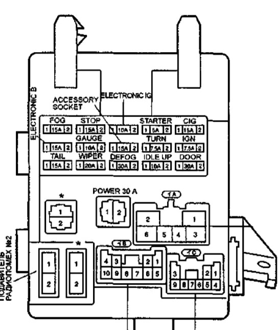
Check the diagrams with your own on the protective cover of the unit.
Appointment
| LECTRONIC-B (ECU-B) | 15A Airbags (SRS), seat belt pretensioners, radio and rear view system |
| STOP | 15A Electronic control unit for automatic transmission and engine, anti-lock braking system (ABS), key lock system in the ignition lock, brake lights. |
| Accessory socket | 15A Optional equipment |
| POWER | 30A Hatch, power windows |
| DOOR | 30A Central locking and key locking system in the ignition lock |
| FOG | 15A Fog lights, engine management system and automatic transmission |
| TAIL | 15A Engine and automatic transmission control system, instrument cluster, tachometer, fog lights, warning system about unplugged lighting and left key in the ignition lock, backlight, dimensions. |
| CIG | 15A Exterior mirrors, airbags, key locking system in the ignition lock, cigarette lighter, radio tape recorder, rear view camera, warning system about unplugged lighting and left key in the ignition lock, additional equipment |
| TURN | 7,5A Emergency signaling, direction indicators |
| DEFOG | 30A Heated rear door glass |
| GAUGE | 10A Charging system, engine management and automatic transmission system, 4WD system, anti-lock braking system (ABS), instrument cluster, warning system for lights not turned off and left key in the ignition lock, air conditioning, reversing lights, warning system for unfastened seat belts, power windows, sunroof control system, central locking, radio, rear view system, tachometer |
| ELECTRONIC-IG | 10A Cooling fan motor, anti-lock braking system (ABS), ignition key lock system. |
| (ECU-IG) | |
| WIPER | 20A Windshield and rear door glass cleaner and washer |
| STARTER | 5A Starting system, ignition system, engine and automatic transmission control system, instrument cluster |
| IDLE-UP | 10A Engine management system and automatic transmission, rear door glass heater |
| IGN | 7.5A Charging system, engine management system and automatic transmission, airbags, instrument cluster |
| CDS FAN | 30A Air conditioner condenser fan |
Some relays can be mounted on the back of the unit: size relay, integrated relay.
Mounting block No. 4
In the diagram it is indicated under the number 18.
Diagram

- R1 – Relay for electric heater fan
- R2 – Main heater relay
Driver side relay box
On the diagram it is indicated under the number 14.
Diagram

Designation
- Main power relay
- Accessory power relay
- Fuel pump relay
- Turn signal relay
Engine compartment
Location
General arrangement of boxes under the hood

Decoding
- ABS electronic control unit and pressure modulator (up to 04.1999)
- ABS relay box (up to 04.1999)
- mounting box # 2 (J / B # 2)
- relay and fuse box No. 5 (R / B No. 5)
- right front airbag sensor (from 04.1998)
- Left front airbag sensor (from 04.1998)
Mounting box No. 2
Photo – an example and a diagram from the block cover
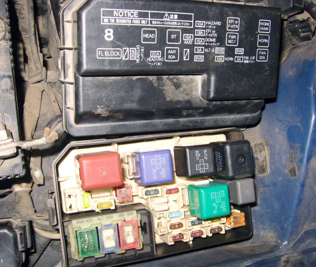
Diagram
Protected components
| 1 | 5А ALT-S – Charging system |
| 2 | 10A HEAD (RH-UPR) – Right headlight (DRL – daytime running lights) |
| 3 | 15A EFI – 4A-FE, 5A-FE, 7A-FE, 4E-FE: Multiport fuel injection system / sequential multiport fuel injection system |
| 15A F-HTR – 2C-E: Multiport fuel injection system / sequential multiport fuel injection system | |
| 4 | 10А HORN – Sound signal, anti-theft system |
| 5 | 10А HAZARD – Hazard warning system, direction indicators |
| 6 | 15A AM2 – Starting system, fuses: “ST”, “IGN” |
| 7 | – |
| 8 | 10A HEAD (LH-UPR) – Left headlight (DRL – daytime running lights) |
| 9 | 15А DOME – Audio system, interior lighting, personal lighting, luggage compartment lighting, clock, daytime running lights, anti-theft system |
| 10 | – |
| 11 | – |
| 12 | – |
| 13 | – |
| 14 | 50А AM1 – Fuses: “CIG”, “TURN”, “GAUGE”, “ECU-IG”, “WIP” |
| 15 | 30A FAN – Cooling fan |
| 30A RDI – Cooling fan | |
| 16 | 40A MAIN – Starting system, fuses: ”HEAD (LH) or HEAD (LH-UPR),” HEAD (RH) or HEAD (RH-UPR), ”HEAD LH-Lo” and ”HEAD RH-LO” |
| 17 | 100А ALT – Fuses: “RDI”, “CDS”, “AM1”, “POWER”, “D / L”, “TAIL”, OBD, “FOG”, “ECU-B”, “STOP”, “DEF” , “HTR” |
| 18 | 50A ABS – ABS |
Relay
| R1 | Engine control unit (ENGINE MAIN) |
| R2 | 4A-FE, 5A-FE, 7A-FE, 4E-FE: Engine control unit (EFI) 2C-E: Fuel heating (F-HTR) |
| R3 | Headlights (HEAD) |
| R4 | Starter (ST) |
| R5 | Sound signal |
| R6 | Cooling fan (FAN NO.1) |
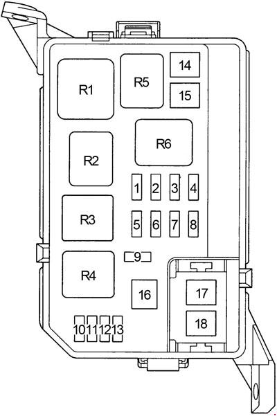
Relay box No. 1
Diagram

Assignment
| 1 | 30A CDS – Cooling fan |
| 2 | 10A HEAD (LH-LWR) – with DRL: Left headlight (DRL – daytime running lights) |
| 3 | 15A HEAD (RH-LWR) – with DRL: Right headlight |
| 4 | 7,5А DRL – Daytime running lights |
| R1 | Dimmer |
| R2 | Cooling fan (AC FAN NO.2) |
| R3 | Cooling fan (AC FAN NO.2) |
| R4 | Air Conditioning Compressor Clutch (AC MG) |
I love too study electric and mechanic parto
What happened if relay integration stops working