The Toyota Celica T230 represents the seventh and final generation of the Toyota Celica range. Produced in 1999, 2000, 2001, 2002, 2003, 2004, 2005 and 2006. Delivered all over the world, so you can find models with both left and right steering. In this article, we will show the locations of the electronic control units, a description of the fuses and relays of the Toyota Celica 230 with box diagrams and photo examples of their execution. Highlight the cigarette lighter fuse.
The location of the boxes and the purpose of the elements in them may differ from the one presented, check the purpose with your diagrams.
Contents
Passenger compartment
Location
General layout of boxes in the cabin
LHD

RHD

Assignment
- Rear fog light relay
- Hazard and turn signal relays
- Front fog light relay
- ’02 -’05: Headlamp leveling control unit
- ’02 -’05: Vehicle stability control unit
- ’99 -’02 (LHD): ABS Control Unit
- Air conditioner control unit
- Fuse box
- Body ECU
- ’02 -’05: Heated Seat Relay
- Airbag control unit
- Key transponder amplifier
- ’02 -’05 (Australia): Headlight range control unit
’99 -’02 (RHD): ABS control unit - ’02 -’05 (RHD): Headlight range control unit
- ’02 -’05 (Australia): Cruise Control Unit
- ’02 -’05 (Australia): Gear selector lock control unit
Fuse box

Diagram

Protected components
| 1 | 15A S / ROOF – Sun roof |
| 2 | 20A FL P / W – Power Windows |
| 3 | 10A STOP – Stop lamps, ABS, auxiliary brake light, multiport fuel injection system / sequential multiport fuel injection system, automatic transmission control unit, cruise control |
| 4 | 7,5A SRS-IG – Airbags |
| 5 | 15A WASHER – Washer of a windshield, washer of a rear window |
| 6 | 15A RADIO – Audio system |
| 7 | 7,5A TURN – Direction indicators |
| 8 | 10A HTR – Air Conditioner |
| 9 | 10A TAIL – Side light, instrument panel light, license plate light |
| 10 | 15A CIG – Cigarette lighter |
| 11 | 25A AM1 – Starting system, fuses: “CIG”, “ECU ACC”, “SRS-IG”, “WASHER”, “WIPER”, “BK / UP LP”, “TENS RDC”, “DEF RLY”, “BODY ECU-IG ”,” TURN “,” HTR “,” WARNING “,” FAN RLY “,” ABS-IG “,” ECU-IG “ |
| 12 | 20A DOOR – Central locking |
| 13 | 15A FR FOG – Front fog light |
| 14 | 7,5A OBD – Diagnostic connector |
| 15 | 25A WIPER – Front wiper |
| 16 | 10A MIR HTR – Heated mirrors |
| 17 | 15A RR WIPER – Rear wiper |
| 18 | 20A FR P / W – Windows |
| 19 | 30A DEF – Heated rear window |
| A | |
| 1 | 7,5A MPX-B – Remote door locks control system |
| 2 | 7,5A RR FOG – Rear fog light |
| 3 | 7,5A DOME – Clock, interior lighting |
| 4 | 7,5A ECU-B – Air conditioning, instrument clu |
| B | |
| 1 | 5A WARNING – Charging system, instrument cluster |
| 2 | 5A ECU-IG – Cruise control |
| 3 | 5A ABS-IG – ABS |
| 4 | 5A FAN RLY – Engine cooling fan |
| C | |
| 1 | 7,5A PANEL 1 – Glove box lighting, instrument panel illumination |
| 2 | 7,5A PANEL 2 – Front fog light, instrument cluster illumination |
| 3 | 7,5A ECU-ACC – Clock, audio system, mirror control unit, antenna |
| 4 | – |
| D | |
| 1 | 5A BK / UP LP – Reversing lamps |
| 2 | 5A DEF RLY – Heated rear window, heated mirrors |
| 3 | 5A BODY ECU-IG – Multiplex unit |
| 4 | 5A TENS RDC – Automatic transmission control unit, gear selector lock, sunroof, aerial |
| Relay | |
| R1 | Ignition (IG1) |
| R2 | Side light (TAIL) |
| R3 | Heated mirrors (MIR HTR) / heater |
| R4 | Heated rear window (DEF) |
The fuse number 10, 15A, is responsible for the cigarette lighter.
Additional elements

- Sunroof relay
- Rear wiper relay
- Central locking receiver
Engine compartment
Location
General arrangement of boxes under the hood

Designation
- Fuse box
- Relay box No. 1
- ’02 -’05: Air pump relay
- ’02 -’05: Headlamp Washer Relay
- Engine control unit (M / T) or engine and transmission control unit (A / T)
- ’02 -’05: ABS & TRC & VSC (with VSC) / ’02 -’05: Vehicle stability control unit (without VSC)
- ’02 -’05: Relay Box # 2
Fuse box
Photo
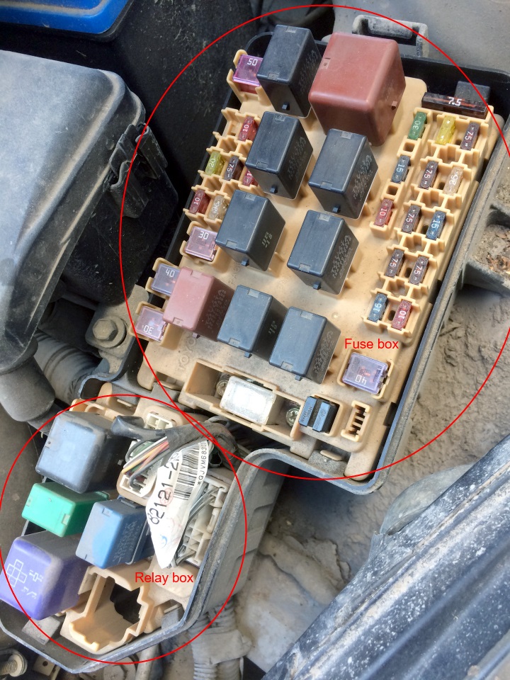
Diagram

Appointment
| 1 | 20A S-HTR – ’02 -’05: Heated seats |
| 15A AUTO ANTENNA – USA: Antenna | |
| 2 | 10A HEAD LH UPR – High beam left |
| 3 | 20A HEAD RH UPR – High beam right (HEAD RH UPR DRL NO.2) |
| 4 | 7,5A HEAD LVL – Daytime running lights, headlight range control |
| 7,5A DRL NO.3 – Daytime running lights | |
| 5 | 10A HEAD RH LWR – ’99 -’02: Low beam right |
| 15A HEAD RH LWR – ’02 -’05: Low beam right | |
| 6 | 10A HEAD LH LWR – ’99 -’02: Low beam left |
| 15A HEAD LH LWR – ’02 -’05: Low beam left | |
| 7 | 25A ABS NO.2 – ABS |
| 8 | – |
| 9 | – |
| 10 | 10A HORN – Sound signal |
| 11 | 7,5A ALT-S – Charging system |
| 12 | – |
| 13 | 10A EFI NO.1 – Multiport fuel injection system / sequential multiport fuel injection system |
| 7,5A EFI NO.1 – Multiport fuel injection system / sequential multiport fuel injection system | |
| 14 | 25A DCC – Fuses: “RADIO”, “DOME”, “MPX-B”, “ECU-B” |
| 15 | – |
| 16 | 7,5A EFI NO.2 – Multiport fuel injection system / sequential multiport fuel injection system |
| 10A EFI NO.2 – Multiport fuel injection system / sequential multiport fuel injection system | |
| 17 | 20A EFI – Multiport fuel injection system / sequential multiport fuel injection system, fuses: “EFI NO.1”, “EFI NO.2” |
| 15A EFI – Europe 2ZZ-GE: Multiport fuel injection system / sequential multiport fuel injection system, fuses: “EFI NO.1”, “EFI NO.2” | |
| 18 | 7,5A ST – Starting system, multiport fuel injection system / sequential multiport fuel injection system |
| 19 | 7,5A AM2 – Starting system |
| 20 | 15A IG2 – Starting system, multiport fuel injection system / sequential multiport fuel injection system |
| 21 | 15A HAZ – Hazard warning system and direction indicators |
| 10A HAZ – Australia, USA: Hazard warning and direction indicators | |
| 22 | 50A HTR – Air conditioner / heater |
| 23 | 30A RDI – Engine cooling fan |
| 24 | 40A ABS NO.1 – ’99 -’02: ABS |
| 50A ABS NO.1 – ’02 -’05: ABS | |
| 25 | 30A CDS – Engine cooling fan |
| 26 | 40A MAIN – Starting system, daytime running lights, fuse: “ST” |
| 50A MAIN – Europe 2ZZ-GE: Starting system, daytime running lights, fuse: “ST” | |
| 27 | 120A ALT – Cooling system, engine cooling fan, starting system, heated rear window, side light, fuses: “ABS NO.1”, “ABS NO.2”, “HTR”, “FR P / W”, “FL P / W ”,” DOOR “,” OBD “,” STOP “,” S / ROOF “,” MIR HTR “,” FR FOG “,” AM1 “ |
| Relay | |
| R1 | Sound signal |
| R2 | Headlights (HEAD) |
| R3 | Fuel pump (C / OPN)) |
| R4 | Engine control unit (EFI) |
| R5 | Engine cooling fan (FAN NO.1) |
| R6 | Ignition (IG2) |
| R7 | Engine cooling fan (FAN NO.2) |
| R8 | Engine cooling fan (FAN NO.3) |
| R9 | Air conditioner compressor clutch (MG / C) |
Relay box
Diagram
1999-2002

2002 – 2006
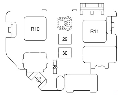
Decoding
- 28 – 10A ETCS – THROTTLE BODY
- 29 – 50A A-PMP – Air Pump
- 30 – 30 / 50A CLN H-LP – Headlight washers
- R10 – Starter (ST)
- R11 – Heater (HTR)
- R12 – ABS (ABS SOL)
- R13 – Motor ABS (ABS MTR)
Relay box 1
Diagram

Assignment
- 1 10A HEAD LH UPR – High beam left
- 2 10А HEAD RH UPR – High beam right, daytime running lights
- R1 – Daytime running lights
- R2 – Daytime running lights
- R3 – Daytime running lights (DRL NO.2 DIMMER)
Relay box 2
Diagram
2002 – 2005

Appointment
- 1 10А – VSC
- R1 – VSC MTR
- R2 – MTR CUT
- R3 – VSC SOL
If you find a mistake or have something to add – write in the comments.