Toyota Camry VX 20 was produced in 1996, 1997, 1998, 1999, 2000, 2001. During this time, the model has been restyled. Also known as Toyota Gracia. In this publication you will find information on the location of electronic control units, a description of fuses and relays Toyota Gracia (Camry 20) with box diagrams and photo examples of their execution. Note the cigarette lighter fuse.
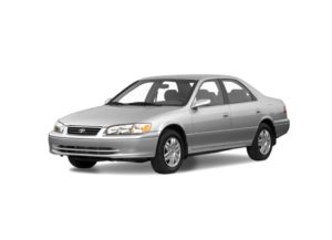
The locations of the boxes and the purpose of the elements in them may differ from the one presented. Check the information with your diagrams on the box cover.
Contents
Passenger compartment
Location
General box layout

Assignment
- Fuse box
- Integral relay
- Turn signal relay
- Cruise control control unit
- Signal amplifier
- Daytime Running Light Main Relay
- Air conditioner amplifier (manual air conditioner)
- Anti-theft system block
- ABS control unit (ABS and Traction)
- Amplifier
- The engine control unit
- Automatic air conditioning control unit
- Central locking unit
- Gear selector lock block
- Central airbag unit
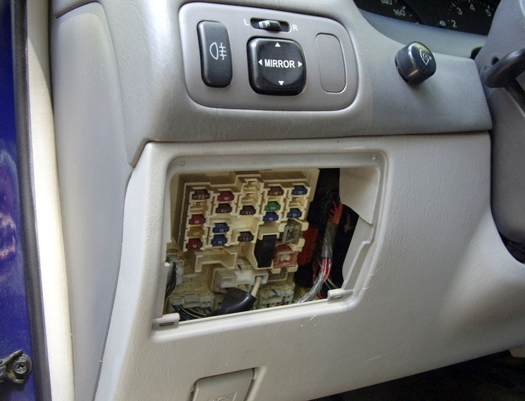
Fuse box
Located at the bottom of the dashboard, behind the glove compartment.
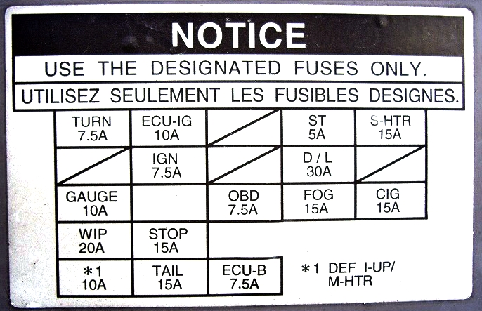
Example of legend from the cover
Diagram
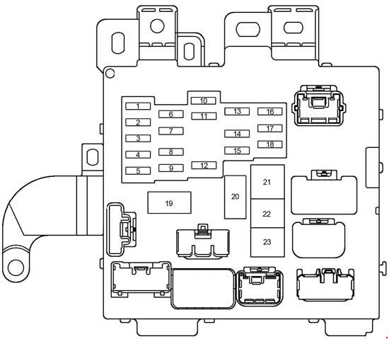
Circuits protected
| 1 | 20A SEAT − HEATER – Heated seats |
| 2 | 10A HEATER – Air conditioning, heated rear window, starting system |
| 3 | 10A GAUGE – Instrument Cluster, Reversing Lights, Cruise Control, Charging System, Daytime Running Lights, Traction Control, Power Windows, Warning Buzzer, Service Indicators |
| 4 | 20A WIPER – 1996-1998: Windscreen wiper and washer |
| 25A WIPER – 1999-2001: Windscreen wiper and washer | |
| 5 | 10A MIRROR − HEATER – Heated mirrors |
| 6 | 15A ECU-IG – Cruise control, anti-lock braking system, aerial, airbags, seat belt pretensioner, anti-theft system, gear selector lock, traction control, daytime running lights, wireless remote control system, fuel injection system |
| 7 | 5A IGN – Instrument Cluster, Charging System, Airbags, Fuel Injection System, Seat Belt Pretensioner |
| 8 | 15A STOP – Stop lamps, cruise control, auxiliary brake light, anti-lock braking system, fuel injection system, gear selector lock |
| 9 | 10A TAIL – Side light, license plate light, daytime running lights, fuel injection system |
| 10 | 15A POWER − OUTLET – Socket |
| 11 | 7,5A OBD – Diagnostic connector |
| 12 | 15A FOG – Fog light |
| 13 | 5A STARTER – Instrument panel, fuel injection system |
| 14 | 25A DOOR – Central locking, anti-theft system, fuel filler flap |
| 15 | 7,5A PANEL – Instrument cluster, audio system, cigarette lighter, glove box lighting, instrument panel light, clock, service indicators, air conditioning control unit lighting, ashtray lighting, alarm, daytime running lights, seat heating control unit, heated rear window, unit automatic transmission control |
| 16 | 7,5A TURN – Direction indicators |
| 17 | 7,5A RAD − NO.2 – Audio system, antenna |
| 18 | 15A CIG – Cigarette lighter, gear selector lock, mirror control unit, anti-theft system, central locking, airbags, seat belt pretensioner, heated mirrors, air conditioning |
| 19 | Interference filter |
| 20 | Interference filter |
| 21 | 40A DEF – Heated rear window |
| 22 | 30A PWR – Power Windows, Power Seats, Sunroof |
| 23 | 40A AM1 – 1996-1999: Headlight washer |
| 40A AM1 – 2000-2001: Fuses: POWER-OUTLET, CIG, RAD-NO.2, TURN, WIPER, ECU-IG, GAUGE and HEATER |
The fuse number 18 at 15A is responsible for the operation of the cigarette lighter.
Some relays are attached to the back of the unit.
Scheme

Designation
- R1 Power relay (power windows, sunroof, power seats)
- R2 Heated rear window
- R3 Side light
- R4 Integrated relay
Additional elements
Diagram

Appointment
- Relay and sunroof control unit
- Airbag sensor
- Antenna control unit
- Airbag sensor
- Lamp failure control unit
Engine compartment
Location
General box layout

Decoding
- Fuse and relay box
- Fuse and relay box 1 (left)
- Fuse and relay box 2 (right)
- ABS control unit and actuator
Fuse and relay box
Photo

Diagram

Assignment
| 1 | 25A A / F HTR – 1999-2001: Air-Fuel Ratio Sensor |
| 2 | Not used |
| 3 | 10A A / C – Air Conditioning |
| 4 | 10A Spare fuse |
| 5 | 15A Spare fuse |
| 6 | 30A Spare fuse |
| 7 | 30A CDS – Cooling fan |
| 8 | 30A RDI – Cooling fan |
| 9 | 5A ALT − S – Battery charging system |
| 10 | 15A HEAD (RH) – 1996-1999: Right Headlight (High Beam) |
| 20A HEAD (RH) – 2000-2001: Right headlight (high beam) | |
| 11 | 15A EFI – Fuel injection system |
| 12 | 10A HORN – Horn, anti-theft system |
| 13 | 10A HAZ – 1996-1999: Alarm |
| 15A HAZARD – 2000-2001: Emergency signaling | |
| 14 | 30A AM2 – Instrument panel, airbags, seat belt pretensioner, fuel injection system, fuses: IGN “and STARTER” |
| 15 | 5A TEL – Phone |
| 16 | 15A HEAD (LH) – 1996-1999: Left headlight |
| 20A HEAD (LH) – 2000-2001: Left headlight | |
| 17 | 20A RADIO NO.1 – Audio system |
| 18 | Not used |
| 19 | 40A MAIN – 1996-1998: Fuses: HEAD (RH-HI), HEAD (RH-LO) |
| 20 | 7,5A DOME – Anti-theft system, daytime running lights, clock, ignition switch lighting, wireless remote control system, interior lighting, luggage compartment lighting, sunroof, personal lighting, central locking, vanity mirror lighting, door lighting |
| 21 | 7.5A ECU − B – 1996-1997: Cruise Control, Antilock Braking System, Airbags |
| 10A ECU − B – 1998-2001: Cruise Control, Antilock Braking System, Airbags, Seat Belt Pretensioner | |
| 22 | 100A ALT – Fuses: RDI and CDS |
| 23 | Not used |
| 24 | 50A HTR – Fuses: AM1 and A / C |
| 25 | 30A T − STK / CDS 2 |
| Relay | |
| R1 | A / C Compressor Clutch |
| R2 | (Circuit Opening) |
| R3 | Cooling fan (no. 2) |
| R4 | Cooling fan (no. 3) |
| R5 | Air conditioning |
| R6 | Main relay |
| R7 | Engine control unit (EFI) |
| R8 | Headlights |
| R9 | Starter |
| R10 | Sound signal |
| R11 | Cooling fan (No.1) |
Fuse and relay box 1
Diagram

Designation
| 1 | Not used |
| 2 | 5A DRL NO.2 – Daytime running lights |
| 3 | 10A HEAD (LH-LO) – Left headlight (low beam) |
| 4 | 10A HEAD (RH-LO) – Right headlight (low beam) |
| Relay | |
| R1 | Headlights (DIM) |
| R2 | Daytime Running Lights |
| R3 | Fuel-air mixture sensor |
Fuse and relay box 2
Diagram
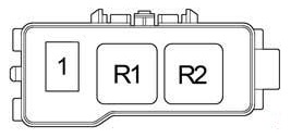
Decoding
1 – 60A ABS
R1 – ABS motor relay
R2 – Relay ABS
 FuseAndRelay.com
Thanks for this information. I could not find any detail on relays elsewhere.
Tom Glass