Toyota Mark 2 in 110 body represents the 9th generation of the model range, produced on a common basis with Toyota Verossa in 2000, 2001, 2002, 2003, 2004, 2005, 2006, 2007. In this publication, we will show the location of the electronic control units, describe the fuses and relays of the Toyota Mark 2 110 with box diagrams and photo examples of execution. Highlight the cigarette lighter fuse.

Check the purpose of the elements with your diagrams on the box cover.
Contents
Passenger compartment
Location
General layout of boxes in the cabin

Assignment
- electronic control unit for automatic transmission (models from 10.2002)
- acceleration sensor (front left)
- navigation system electronic unit
- router
- central mounting block
- chassis electrical unit
- TEMS electronic unit
- passenger side mounting block
- amplifier transponder
- stability control (VSC) buzzer
- electronic control unit SRS
- driver’s side mounting block
- Selector lever lock electronic control unit
- deceleration sensor (4WD)
- deceleration sensor lateral movement sensor (with VSC)
Fuse box
Under the panel on the driver and passenger side, there are 2 fuse boxes and are covered with protective covers.

Driver side box

Diagram from the box cover

Diagram

Designation
CORNERING LAMP 5A turn lights STARTER 5A launch system GAUGE 5A charging system IG1 7.5 A electric fan drive BACK-UP 7,5A IGN 10A engine management system REAR WIPER 10A rear window cleaner and washer WASHER 15A windshield wiper and washer ECU-IG 15A anti-lock braking system (2WD models without TRC and without VSC) STOP 15A brake lights CIG 15A cigarette lighter D FRONT POWER WINDOW 20A Power windows (models manufactured before 05.2003) IG2 20A ignition system WIPER 20A windshield wiper and washer D POWER SEAT 30A electric driver’s seat |
The cigarette lighter fuse is marked as CIG, circled in red in the diagram.
Passenger side box

Example of a diagram from the box cover
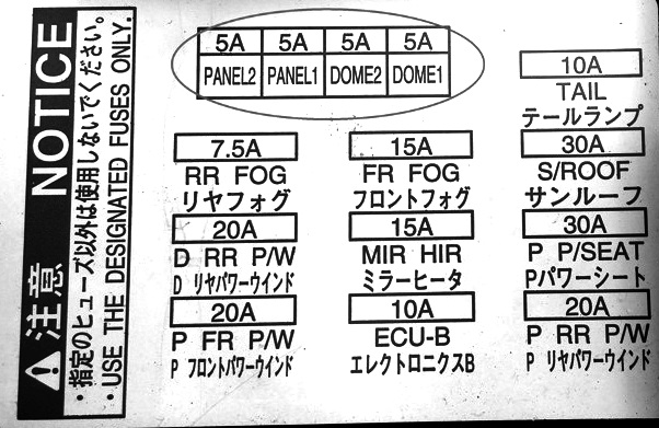
Diagram

Appointment
DOME1 5A interior lighting lamps DOME2 5A watch PANEL1 5A watch PANEL 25A backlight REAR FOG 7.5A fog lights (rear) ECU-B 10A engine management system TAIL 10A fog lights (rear) FR FOG 15A fog lights (front) MIRROR HEATER 15A heater of mirrors and defroster of brushes D REAR POWER WINDOW 20A power windows (rear) P FRONT POWER WINDOW 20A power windows (front) P REAR POWER WINDOW 20A electric windows P POWER SEAT 30A electric passenger seat SUN ROOF 30A electric sunroof |
Engine compartment
Location
General arrangement of boxes under the hood

Decoding
- airbag sensor (front right)
- airbag sensor (front left)
- relay and fuse box in the engine compartment
- relay and fuse box in the engine compartment No. 2
- electronic engine control unit
Relay and fuse box
It is on the left side, next to the counter.

Diagram

Assignment
ALT-S 5A charging system H-LPUPR 5A fog lights (sedan) MRH-B 5A charging system А / С 10А automatic air conditioner ETCS 10A engine management system (models with 1JZ-GE engine) H-LPLUPR 15A instrument cluster H-LPRLWR 15A headlights. H-LPRUPR 15A headlights POWER OUTLET 15A connector for additional equipment (station wagon) RADIO No. 1 15A audio system (models released since 12.2003) TEMS 15A direction indicators and hazard warning lights B / DECU 20A MULTIPLEX system DOOR 20A MULTIPLEX system EFI 25A engine control system F / PMP 25A engine management system (models with 1JZ-FSE engine) FRDEF 25A heater of mirrors and defroster of brushes AM2 30A launch system DEFOG 30A rear window heater (station wagon) FAN 30A electric fan drive (models with 1JZ-GE motor) ABS1 40A anti-lock braking system (2WD models without TRC and without VSC) ABS2 40A anti-lock braking system (2WD models without TRC and without UBS) DEFOG 40A rear window heater, (sedan) HTR 40A automatic air conditioner FAN 60A electric fan drive (models with 1JZ-GTE motor) ALT 100 A charging system ALT 100 A electric window regulator (models from 05.2003 onwards) ALT 120 A ALT 140 A charging system |
- R1 – main relay of the injection system
- R2 – starter relay
- R3 – ABS electric pump relay
- R4 – headlight relay
- R5 – fuel pump relay
- R6 – injector relay
- R7 – ABS electric pump relay
- R8 – relay of the ABS electric pump
- R9 – injection system relay
- R10 – high beam relay
Relay and fuse box No. 2
Diagram

Designation
- R1 – TEMS relay
- R2 – Rear window defogger relay
- R3 – Horn relay
- R4 – Air conditioner relay
- R5 – Brush defroster relay
- R6 – Heated mirror relay
- R7 – Fan motor relay
- R8 – Fuel pump relay
- R9 – Fan motor relay
Why my Mark X 2005 v6 engine disappear engine check light and Battery light as you start the car then it comes back later