The Toyota Avanza has been produced since 2003 and spans three generations. In this publication, you’ll find a description of the Toyota Avanza’s fuses and relays, along with fuse box diagrams, their locations, and photo examples. Let’s highlight the cigarette lighter fuse.

The purpose of fuses and relays may differ from that described and depends on the year of manufacture and the level of electrical equipment in your vehicle.
Contents
Passenger compartment
Depending on the year of manufacture, fuse box layouts may vary. We’ll present the two most popular.
Type 1
Located at the bottom of the instrument panel.
Layout
LHD

RHD
Diagram

Assignment
| ST | 7.5A – Starter circuit / ignition switch |
| IG1/BACK | 7.5A – Ignition circuit No.1 / reverse light |
| FR FOG RH | 7.5A – Front fog light (right) |
| FR FOG LH | 7.5A – Front fog light (left) |
| ECU IG1 | 20A – Engine control unit power supply |
| D/L | 15A – Door lock system |
| HAZARD | 10A – Hazard lights / turn signals |
| E/G | 10A – Engine electronics |
| ECU IG2 | 10A – Engine control unit secondary circuit |
| A/C No.2 | 10A – Air conditioning circuit No.2 |
| FR WIP | 20A – Front windshield wiper |
| RR WIP | 15A – Rear windshield wiper |
| DEF | 20A – Rear window defogger |
| CIG | 15A – Cigarette lighter / power outlet |
| ACC | 10A – Accessories (radio, sockets, etc.) |
| POWER | 30A – Main power feed |
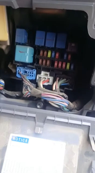
Type 2
Located at the bottom of the instrument panel, on the right side.
Photo for example

Diagram

Designation
| DEF2 | 5A – Rear defogger (secondary) |
| FR FOG LH | 7.5A – Front fog light (left) |
| FR FOG RH | 7.5A – Front fog light (right) |
| POWER B | 20A – Power circuit (battery feed) |
| A/C | 7.5A – Air conditioner control |
| ECU IG1 | 7.5A – Engine control unit (ignition 1) |
| IG1 | 5A – Ignition system circuit |
| AM2 | 7.5A – Ignition power circuit (AM2 relay) |
| ACC | 5A – Accessory circuit |
| H-LP HI RH | 10A – Headlight high beam (right) |
| DOME | 5A – Interior lights / dome lamp |
| H-LP HI LH | 10A – Headlight high beam (left) |
| STOP | 10A – Brake lights |
| TAIL | 10A – Tail / parking lights |
| HORN | 10A – Horn |
| DEF | 15A – Rear defogger |
| POWER | 30A – Main power |
| AM1 | 5A – Ignition main circuit |
| SOCKET | 15A – Power outlet / cigarette lighter |
| BACK UP2 | 5A – Memory / backup circuit |
| FR WIP | 25A – Front wipers |
| H-LP LO LH | 15A – Headlight low beam |
Type 3
Located at the bottom of the instrument panel, on the left side.

Check the purpose of the elements with your diagram on the back of the block cover.

Allocation
| FOG RH | 10A – Front fog light (right) |
| FOG LH | 10A – Front fog light (left) |
| A/C | 7.5A – Air conditioning system |
| HORN | 10A – Horn |
| WASHER | 15A – Windshield washer |
| ACC | 10A – Accessory circuit (radio, etc.) |
| PWR SEAT | 20A – Power seat system |
| DEF NO.2 | 10A – Rear window defogger (secondary) |
| ECU-IG1 | 7.5A – Engine control unit (ignition 1) |
| METER-IG1 | 10A – Instrument cluster / meter power |
| STOP | 10A – Stop lamps (brake lights) |
| OUTLET | 15A – Power outlet / cigarette lighter |
| DOME | 10A – Interior light circuit |
| TAIL | 10A – Tail and parking lights |
| AM2 | 7.5A – Ignition power supply (AM2 relay) |
| OBD | 7.5A – Diagnostic connector / OBD port |
| WIPER | 25A – Front windshield wiper |
| P/W | 20A – Power windows |
| AM1 | 5A – Ignition main circuit |
| STRG LOCK | 20A – Steering lock system |
| SPARE | 5A / 10A / 20A / 15A – Reserved spare fuse slots |
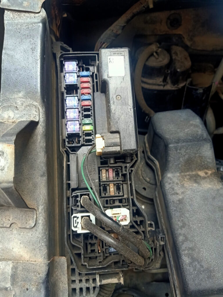
Engine compartment
The fuse box is located near the battery.
Layout

Type 1
Diagram

Appointment
| AM2 | 30A – Ignition system main power (AM2 circuit) |
| ABS | 40A – Anti-lock brake system main fuse |
| PWR | 30A – Main power supply |
| HTR | 40A – Heater / blower motor circuit |
| EPS | 50A – Electric power steering |
| RAD | 30A – Radiator fan motor |
| BACK UP | 15A – Backup / memory circuit |
| FUEL PMP | 10A – Fuel pump |
| HAZ | 10A – Hazard lights / turn signals |
| A/C | 10A – Air conditioning system |
| EFI | 15A – Electronic fuel injection system |
| ETCS | 10A – Electronic throttle control system |
| RR FOG | 5A – Rear fog lamp |
| ACC RR | 15A – Rear accessory power outlet |
| ABS2 | 30A – Secondary ABS circuit |
| IG MAIN | 20A – Ignition main relay |
| ECU IG2 | 5A – Engine control unit (ignition 2) |
| ST | 5A – Starter signal circuit |
| E/G | 10A – Engine control system |
| IG/BACK | 5A – Ignition and backup circuit |
| SPARE | 5A / 10A / 15A – Reserved spare fuses |
Type 2
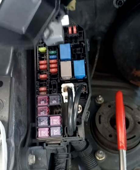
Digram from the covery
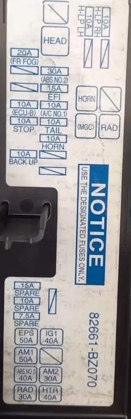
Decoding
| FR FOG | 20A – Front fog lights |
| HEAD | 10A – Headlight control circuit |
| H-LP RH | 10A – Headlight (right) |
| H-LP LH | 10A – Headlight (left) |
| STOP | 10A – Stop lights (brake lights) |
| TAIL | 10A – Tail and parking lights |
| HORN | 10A – Horn circuit |
| BACK UP | 10A – Backup / memory power |
| EFI | 15A – Electronic fuel injection system |
| A/C NO.1 | 10A – Air conditioning circuit |
| ECU-B | 10A – Engine / body ECU power |
| ABS NO.2 | 30A – ABS control system secondary circuit |
| MGC | Magnetic clutch (A/C compressor) |
| RAD | Radiator fan motor circuit |
| EPS | 50A – Electric power steering |
| AM1 | 50A – Ignition main feed |
| ABS NO.1 | 40A – Primary ABS circuit |
| IG1 | 40A – Ignition power circuit |
| AM2 | 30A – Secondary ignition circuit |
| HTR | 40A – Heater / blower motor circuit |
| RAD | 30A – Radiator fan motor |
| SPARE | 15A / 10A / 7.5A – Spare fuse slots |
Type 3

Diagram

Description
| HTR | 40A – Heater (blower motor) |
| RDI | 30A – Radiator fan motor (primary) |
| ST | 30A – Starter motor |
| ABS | 40A – Anti-lock brake system |
| EPS | 50A – Electric power steering |
| ABS NO.2 | 30A – ABS secondary circuit |
| BKUP LP | 15A – Back-up / tail lamps |
| FUEL PMP | 10A – Fuel pump |
| H-LP RH | 10A – Headlamp right |
| H-LP LH | 10A – Headlamp left |
| HAZ | 10A – Hazard / turn signal |
| EFI | 15A – Electronic fuel injection |
| ETCS | 10A – Electronic throttle control |
| ENG | 10A – Engine control circuit |
| ECU-IG2 | 5A – ECU ignition feed |
| TAIL | 10A – Tail lights |
| RR FOG | 5A – Rear fog light |
| ACC RR | 15A – Rear accessory power |
| IG MAIN | 20A – Ignition main |
| SPARE | 5A / 10A / 15A – Spare slots |
| ST Relay | Starter relay |
| RDI Relay | Radiator fan relay |
| RDI NO.2 Relay | Secondary radiator fan relay |
We have also prepared a video on this topic on our YouTube channel.