Suzuki Escudo 3rd generation was produced in 2006, 2007, 2008, 2009, 2010, 2011, 2012, 2013, 2014, 2015. Also known as Suzuki Grand Escudo 3. In this article you can find a description of the fuses and relays of the Suzuki Escudo 3 with fuse box diagrams, photographs and their locations. Note the cigarette lighter fuse.

The design of the boxes and the number of elements in them in your Suzuki may differ from the one presented and depend on the year of manufacture and the level of vehicle equipment.
Engine compartment
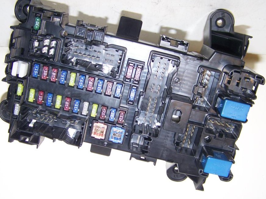
Main fuse box

Located on the left side, next to the counter. Closed with a protective cover.
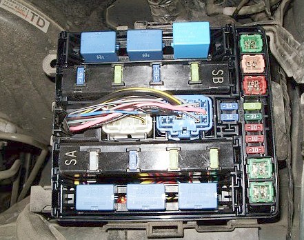
The current assignment of fuses and relays will be presented in the form of a diagram on the back of the cover.

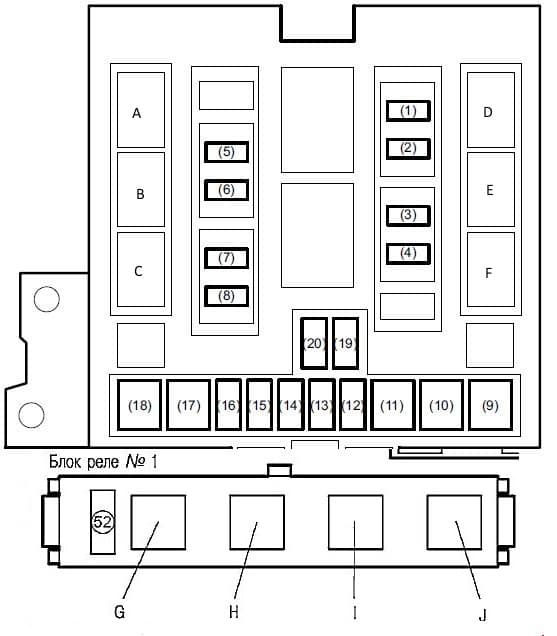
Diagram
Designation
| 1 | 15A Air conditioning electromagnetic clutch |
| 2 | 20A Oxygen sensor heater |
| 3 | 15A Electric throttle |
| 4 | 20A automatic transmission |
| 5 | 25A Heated rear window |
| 6 | 15A Sound signal |
| 7 | 20A Fog lights |
| 8 | 20A Heated mirrors |
| 19 | 15A Left headlight (low beam), left discharge headlight, low beam headlamp relay |
| 20 | 15A Right headlight (low beam), right gas discharge headlight, low beam headlamp relay |
| 9 | 40A Heater fan |
| 10 | 30A ABS control unit 2, ESP control unit |
| 11 | 50A ABS control unit 1, ESP control unit |
| 12 | 20A Main relay |
| 13 | 30A Electro headlight washer pump |
| 16 | 10A Left headlight (high beam) |
| 15 | 10A Right headlight (high beam) |
| 16 | 10A High beam relay, low beam relay |
| 17 | 40A Starter ST |
| 18 | 40A Ignition switch IGN |
Relay
| A | Headlamp high beam relay |
| B | Headlamp low beam relay |
| C | Starter relay |
| D | Fuel pump relay |
| E | the main thing |
| F | Heater fan motor |
| G | Electric throttle valve |
| H | Cooling system fan motor No. 1, 2, 3 |
| I | |
| J | |
| K | Brake light relay |
Additional relay box
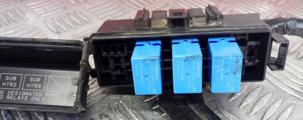
Additional box
It is not far from the battery and consists of power fuses.

Diagram
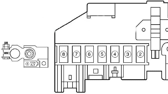
Assignment
| 1 | 120 / 80A All circuits, battery, fuse box # 1 |
| 2 | 30 / 40А Cooling system fan motor relay No. 2 and No. 1 |
| 3 | |
| 4 | 40A 4WD control unit |
| 5 | 50A Ignition lock |
| 6 | 60A Fuse box No. 2, low beam relay, mounting block |
| 7 | Integrated relay box # 1, integrated relay box # 2, fuse box # 2 |
| 8 | Fuse box No. 2 |
Passenger compartment
Mounted on the left pillar, on the driver’s side, under the dashboard.

The photo
The current diagram will be printed on the protective cover of the unit.
Diagram
Appointment
| 1 | Tailgate relay |
| 2 | Relay for auxiliary ignition circuits |
| 3 | Transmission selector lock relay (“P” range) |
| F1 | (20A) Alternator, ignition coils, engine ECU |
| F2 | (10A) ECM, instrument cluster |
| F3 | (15A) ECM, display, audio system |
| F4 | (20A) Central locking |
| F5 | (10A) Rear dimensions |
| F6 | (15A) Interior lamp |
| F7 | (25A) SunRoof |
| F8 | (20A) Electronic engine control module (ECM) |
| F9 | (7.5A) Starting system |
| F10 | (15A) Hazard warning lamp, turn signal interrupter relay |
| F11 | (7.5A) Vanity mirror lamp |
| F12 | (30A) Power windows |
| F13 | (20A) Power windows |
| F14 | (15A) Airbag |
| F15 | (10A) ABS, ESP control unit, steering angle sensor |
| F16 | (10A) Reversing light, selector position sensor, headlight range control switch |
| F17 | (15A) Cooling system fan motor relay # 1, # 2 and # 3 |
| F18 | (20A) Windshield wiper |
| F19 | (15A) Cigarette lighter fuse, charging connector |
| F20 | (10A) Cruise control, Brake light switch |
| F21 | (15A) Charging connector |
| F22 | (7.5A) Rear fog lamps, Combi switch |
| F23 | (15A) Stop lights |
For the front cigarette lighter fuse number 19 at 15A is responsible, and for additional sockets – 21 at 15A.
On our YouTube channel, we also posted a video. Watch and subscribe.
That’s all, and if you have something to add, write in the comments.