Renault Trafic 3 rd generationwas produced in 2015, 2016, 2017, 2018, 2019, 2020, 2021, 2022 and currently. This description of the fuse and relay boxes is also suitable for Nissan Primastar owners, since they have a common base. Let’s denote the cigarette lighter fuse.

The number of elements in the boxes may differ from that shown and depends on the year of manufacture and the region of delivery. Check the description with your technical documentation.
Passenger compartment
Fuse box
It is located on the left side of the instrument panel – behind the cover on the LHD vehicles.

Diagram

Or in the glove box on the RHD.
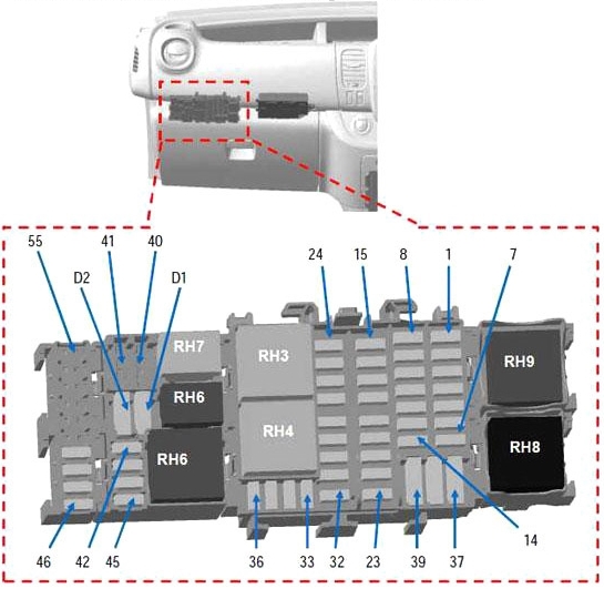
the photo

Assignment
| F1 | 30A + battery feed rear window wiper |
| F2 | 10A Main electromagnetic horn |
| F3 | 15A + battery feed boot accessories socket |
| F4 | 30A + battery feed driver’s window lift motor time delay |
| F5 | 15A + current distribution rear accessories socket |
| F6 | 5A BCM start-up + |
| F7 | 15A + after ignition feed heated seats |
| F8 | 5A + EMM battery feed (after ignition feed charge on VSC) AVS,AUO |
| 15A + EMM battery feed (after ignition feed charge on VSC) SOP03C | |
| F9 | 5A + overall current distribution |
| F10 | 15A + cigarette lighter socket or front accessory socket current distribution |
| F11 | 25A + EMM battery feed (R daytime running lights, front position, R main beam headlights, L dipped beam headlights) |
| F12 | 5A + timed battery feed brake lights, ABS, transponder |
| F13 | 10A + timed battery feed interior lights and air conditioning |
| F14 | 5A + timed battery feed steering wheel angle Stop and Start keyless vehicle |
| F15 | 25A + After ignition feed rear window wiper, window washer pump, horn |
| F16 | 10A Overall + after ignition feed |
| F17 | 5A + after ignition feed reverse gear lights |
| F18 | 5A + after ignition feed stop switch |
| F19 | 5A + after ignition feed injection, starter relay, BCM |
| F20 | 5A + after ignition feed airbag, column lock |
| F21 | 30A + after ignition feed passenger window lift switch |
| F22 | 10A + after ignition feed power steering pump |
| F23 | 15A + EMM battery feed brake lights |
| F24 | 15A + battery feed BCM (+ timed battery feed) |
| F25 | 10A + battery feed BCM, electronic calculation units tyre pressure monitoring system and keyless vehicle |
| F26 | 15A + battery feed BCM for hazard warning and direction lights |
| F27 | 25A + battery feed BCM for locking of opening elements |
| F28 | 25A + EMM battery feed for L daytime running lights, rear position, Lmain beam headlights, R dipped beam headlights |
| F29 | 25A + EMM battery feed number plate position, front and rear fog lights |
| F30 | 15A + battery feed single lever, alarm, horn |
| F31 | 5A + battery feed dashboard |
| F32 | 5A + battery feed single lever |
| F33 | 20A + battery feed tow bar socket preequipment |
| F34 | 15A (supplied in tow bar kit) |
| F35 | 5A + battery feed circuit breaker radio, multimedia, mirrors, fault finding socket |
| F36 | 5A + feed mirror heater |
| F37 | 10A + timed battery feed electric mirrors, additional adapter unit UCE |
| F38 | 40A + battery feed circuit breaker tachygraphy |
| F39 | 40A + battery feed windscreen wiper |
| F40 | 20A + battery feed current distribution relay 1 (heating, air conditioning) |
| F41 | 15A + current distribution feed pre-equipment additional adaptations |
| F42 | 10A + battery feed heater |
| F43 | 10A + feed engine running additional adaptation |
| F44 | 25A + feed engine running heater |
| F45 | 25A + after ignition feed additional air conditioning unit |
| F46 | 25A + after ignition feed relayed for keyless vehicle |
| F47 | 20A + EMM battery feed for non-load shed current distribution relay |
| F48 | – |
| F49 | – |
| F50 | – |
| F51 | – |
| F52 | – |
| F53 | – |
| F54 | – |
| F55 | – |
The fuse number 10 at 15A is responsible for the cigarette lighter.
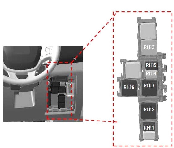
Relay box
The additional relay box is on the right side – in the glove box on the LHD.

Or behind the cover on the RHD.
Designation
| RH3 | 40A Windscreen wiper relay |
| RH4 | 40A Windscreen wiper 2nd speed relay |
| RH5 | 40A + after ignition feed relay heating and rear air conditioning |
| RH6 | 20A Support relay water pump heater matrix |
| RH7 | 20A Driver’s door electrical unlocking relay (SDO) |
| RH8 | 70A + current distribution relay no. 1 |
| RH9 | 40A + current distribution relay no. 2 |
| RH11 | 20A Electric window lift relay |
| RH12 | 40A Mirrors + rear window heater relay |
| RH13 | 40A Rear window wiper relay |
| RH14 | 20A Door central locking relay |
| RH15 | 20A Electric window lift relay |
| RH16 | 40A After ignition feed relay no. 2 (hands-free card vehicles) |
| RH17 | 40A Engine running + relay |
| RH18 | – |
| RH19 | – |
| RH20 | – |
Engine compartment
Located on the left, next to the battery.
For example

Diagram

Protected components
| F1 | – | – |
| F2 | – | – |
| F3 | 25 | ABS/ESP |
| F4 | 30 | Starter |
| F5 | 70 | Passenger compartment 1 |
| F6 | 70 | Passenger compartment 3 |
| F7 | 50 | ABS/ESP |
| F8 | 60 | Passenger compartment 2 |
| F9 | 20 | Mirrors heater |
| 40 | Rear window + mirrors heater | |
| F10 | – | – |
| F11 | – | – |
| F12 | – | – |
| F13 | – | – |
| F14 | 15 | + battery feed air conditioning compressor |
| F15 | 15 | Fuel pump |
| F16 | 70 | Heater control unit |
| F17 | 60 | Heating element unit |
| F18 | 60 | Heating element unit |
| F19 | 40 | Engine suffix *408 and air conditioning or 450 and heating Motor-driven fan assembly 1 |
| 50 | Engine suffix *408 and heating or 450 and air conditioning Motor-driven fan assembly 1 | |
| F20 | 40 | Engine suffix *408 and air conditioning or 450 Motor-driven fan assembly 2 |
| F21 | – | – |
| F22 | – | – |
| F23 | – | – |
| F24 | – | – |
| F25 | – | – |
| F26 | 25 | Diesel heater |
| F27 | 20 | Engine injection system |
| F28 | 15 | Engine injection system |
| Relay | ||
| R1 | 20 | Starting |
| R2 | 20 | Fuel pump relay |
| R3 | 40 | Injection supply relay |
| R4 | 20 | Compressor control relay |
| R5 | – | – |
| R6 | 70 | Highspeed (Motor-drivenfan assembly 1) |
| R7 | 40 | Low speed (Motor-driven fan assembly) |
| R8 | 40 | Highspeed (Motor-drivenfan assembly 2) |
| Diodes | ||
| D1 | Air conditioning compressor | |
| D2 | – | |
Electrical distribution unit
Located near the battery itself.
Diagram
 Assignment
- Battery protection supply wiring
- 300A Engine wiring (Alternator)
- 300A Engine wiring (starter motor)
- 5A Mini fuse with cap (Start/Stop)
- 5A Cab wiring (Start/Stop)
- 50A Cab wiring (conversion KPD and KC6 options or trailer tow bar)
- Reserved for purpose-body builder conversions
- 35A Engine wiring (engine management)
- Engine Connection Unit
- 120A Cab wiring (power steering)
If you want to help supplement the material – write in the comments.
Hi I have a message code on dash, daylight running lights short circuit or open circuit, any help would be much appreciated, thank you.